 50.002 CS
- ALU
- Task 1: Adder Unit
- Task 2: Compare Unit
- Task 3: Boolean Unit
- Task 4: Shifter
- Task 5: Multiplier
- Task 6: Assembling the ALU
- Better ALU Tester
- Compile and test on Hardware
- Summary
50.002 Computation Structures
Information Systems Technology and Design
Singapore University of Technology and Design
(Verilog) Lab 5: Arithmetic Logic Unit
This is a Verilog parallel of the Lucid + Alchitry Labs Lab 5. It is not part of the syllabus, and it is written for interested students only. You still need to complete all necessary checkoffs in Lucid, as stated in the original lab handout.
If you are reading this document, we assume that you have already read Lab 4 Lucid version, as some generic details are not repeated. This lab has the same objectives and related class materials so we will not paste them again here. For submission criteria, refer to the original lab 5 handout.
ALU
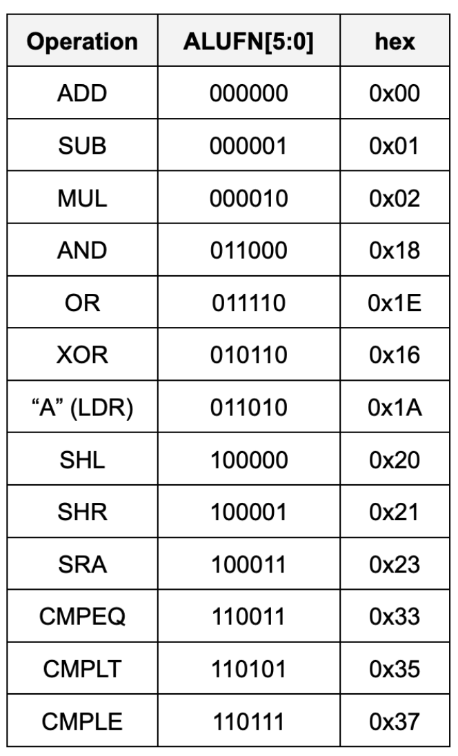
The ALU can perform the following 13 arithmetic operations based on ALUFN signal given as an input:
We shall implement the ALU using basic boolean operations only, and not take shortcuts like using +/- to implement adder/subtactor unit for the sake of learning.
Task 1: Adder Unit
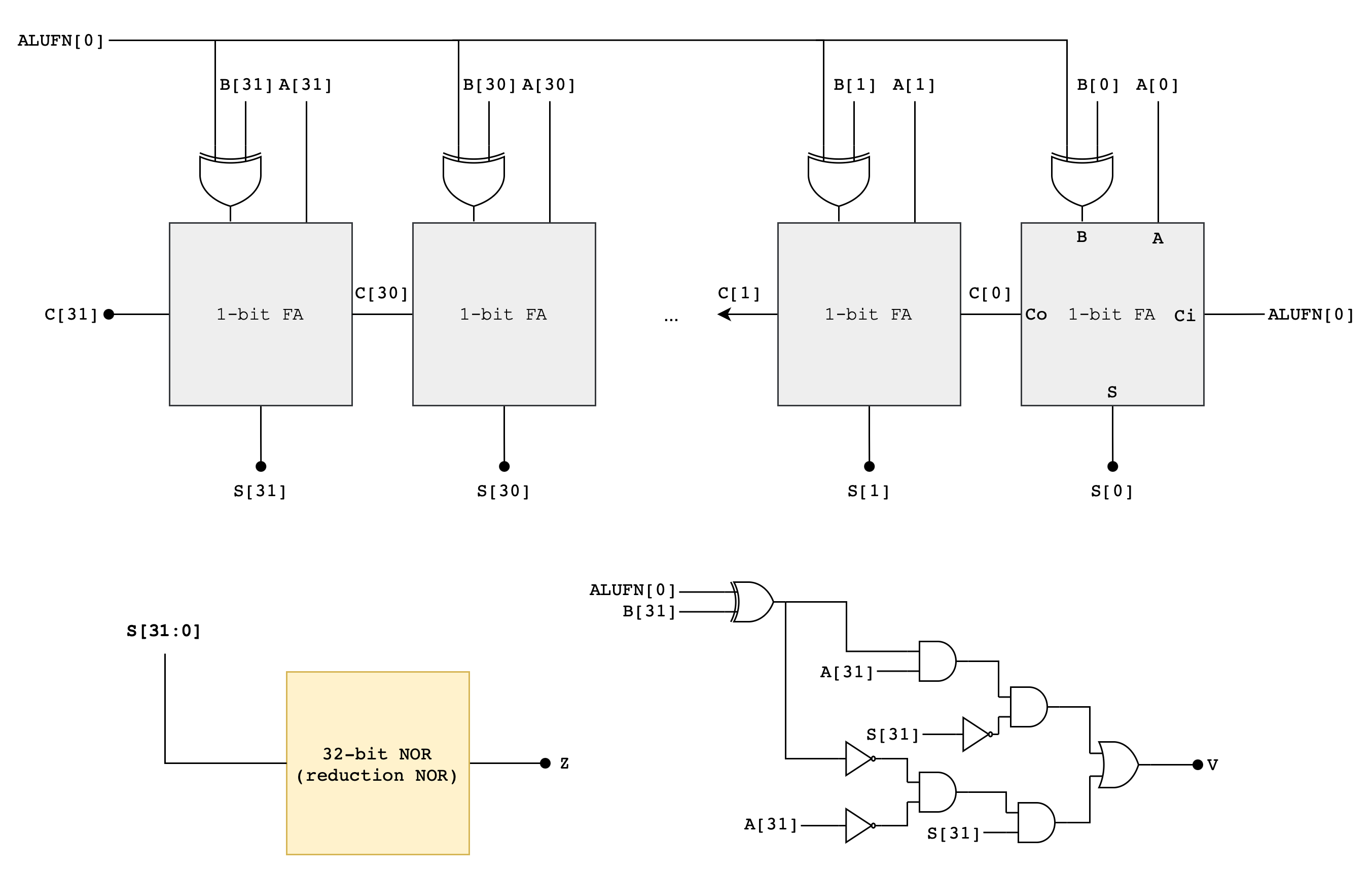
Implement an adder/subtractor unit that can add or subtract 32-bit two’s complement (SIGNED) inputs (A[31:0], B[31:0]). It should generate a 35-bit output: (S[31:0]) andZ, V, N signals. A[31:0] and B[31:0] are the 32-bit two’s complement (SIGNED) input operands and S[31:0] is the 32-bit signed output. Z/V/N are the three other output code bits described below:
Zwhich is true when the S outputs are all zero (i.e.,NOR(S) == 1 ? Z = 1 : Z = 0)Vwhich is true when the addition operation overflows (i.e., the result is too large to be represented in 32 bits), andNwhich is true when the S is negative (i.e.,S[31] == 1 ? N = 1 : N = 0).
Z, V, N will later be used by the comparator unit (read next section). The following diagram illustrates a suggested implementation of the 32-bit Adder/Subtractor Unit using a Ripple Carry Adder (RCA):
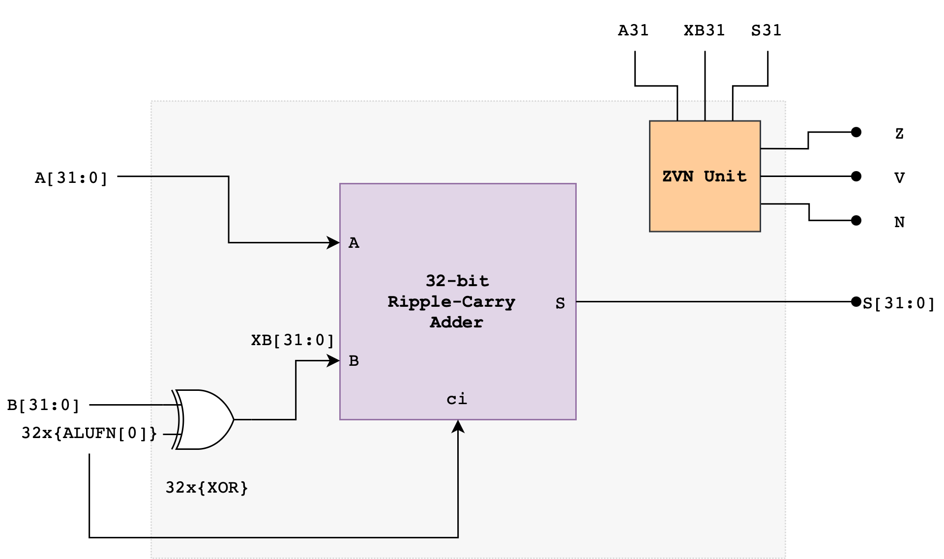
The ALUFN0 input signal controls whether the operation is an ADD or SUBTRACT. ALUFN0 will be set to 0 for an ADD (S = A + B) and 1 for a SUBTRACT (S = A – B). To perform a SUBTRACT, the circuit first computes the two’s complement of the B operand before adding the resulting value with A. The two’s complement of B is computed using the XOR gate and ALUFN0 as carry in to the first Full Adder in the RCA.
The Ripple Carry Adder
A Ripple Carry Adder (RCA) is a simple binary adder that consists of multiple full adders (FA) connected in series. It is used to add two binary numbers. You have met this device in the previous lab.
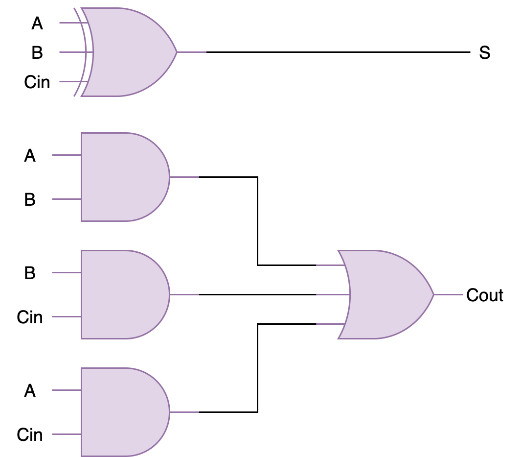
A full adder (FA) schematic is as shown:
To build a 32-bit RCA, you can connect 32 of these in series to form a 32-bit ripple-carry-adder. Below is an example of 4-bit ripple-carry-adder from the previous lab for your reference:
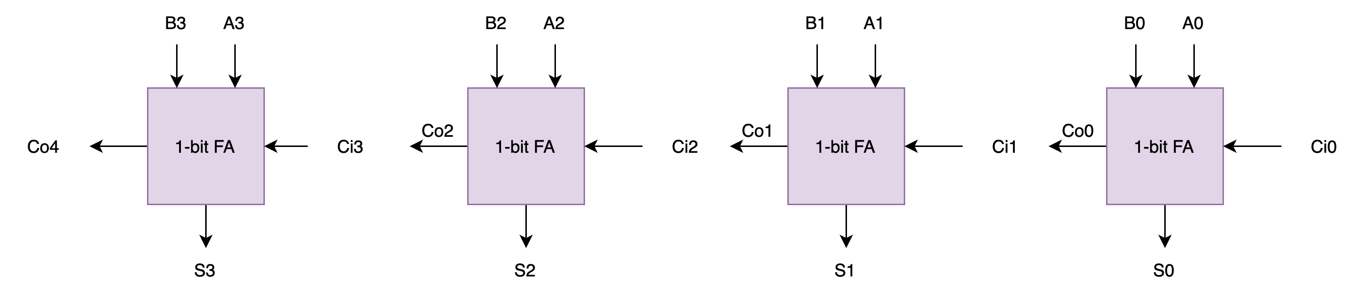
If you haven’t done it in the previous lab, you are encouraged to create the ripple carry adder as a standalone module that accepts the number of operands bits (e.g: SIZE) supported as the PARAMETERS.
Computing Overflow: V
What is overflow?
Overflow happens when the number of bits required to represent the signed result exceeds the hardware’s capability. There are two types of overflow: positive and negative.
Positive and negative overflow refer to specific types of integer overflow that occur when the result of an arithmetic operation exceeds the maximum or falls below the minimum value representable by a given number of bits for a signed integer type. This causes the value to “wrap around” to the opposite end of the range.
For example, consider a signed 4-bit adder. It can represent numbers from -8 to 7. If we let
a = 0111(7) andb = 0110(6) and add them together, it should result ins = 01101(13). However, since the hardware only supports 4-bit, we only see the result ass = 1101(-3). This is a positive overflow: where addition of two positive numbers yield a negative result.Now, can you come up with an example of negative overflow? That is where addition of two negative numbers yield a positive result.
Notice that overflow can never occur when the two operands to the addition have different signs. If the two operands have the same sign, then overflow can be detected if the sign of the result differs from the sign of the operands.
\[\begin{align*} V = &A_{31} \cdot XB_{31} \cdot \overline{S_{31}} + \overline{A_{31}} \cdot \overline{XB_{31}} \cdot S_{31} \end{align*}\]Note that we use XB, not B, that’s the output of the XOR gate (B XOR ALUFN[0]) shown in the adder schematic above.
Computing Overflow
VWhy is
Vcomputed like the above? Start by having a small example, let’s say a 4-bit RCA. If we haveA: 0111, andB: 0001, adding both values will result in a positive overflow. The true answer to this should be decimal8. With signed devices, we need 5 bits to represent decimal 8:01000. However since our RCA can only output 4-bits, we have our output as just1000, and this means decimal -8 in a signed 4-bit output. Now think about other possible overflow cases (negative overflow, etc).
Detailed Adder/Subtractor Schematic
Here’s the detailed schematic of the adder to get you started:
You may start by making a 1-bit Full Adder module first inside fa.v, and then create a 32-bit RCA module in rca.v. Or if you have completed the previous labs, simply copy it over. Afterwards, assemble everything inside adder.v.
Implementation Tips
This section contains a collection of Verilog syntax that might help you implement the adder/subtractor unit.
for loops in Verilog: procedural vs generate
In Verilog, there are two different “for loops” depending on what you’re trying to do:
- Generate
forloop (builds repeated hardware instances): Use this when you want to instantiate many copies of a module (like chaining full adders).
genvar i;
generate
  for (i = 0; i < 32; i = i + 1) begin : FA_CHAIN
    fa u_fa (
      .a   (a[i]),
      .b   (b[i]),
      .cin (c[i]),
      .sum (sum[i]),
      .cout(c[i+1])
    );
  end
endgenerate
This for is elaboration-time. It “unrolls” into 32 physical fa instances.
- Procedural
forloop (runs insidealwaysblocks): Use this for combinational/sequential logic (often for building buses, priority encoders, etc.). It does not create module instances.
integer k;
always @* begin
  for (k = 0; k < 32; k = k + 1) begin
    y[k] = a[k] & b[k];
  end
end
This for loop is still hardware, but it describes logic equations (connections between instances), not instantiation.
If your goal is “duplicate fa units”, you want generate-for + genvar, not procedural for.
Reduction Operators (with examples)
Reduction operators combine all bits of a vector into one bit.
Example:
wire [3:0] a = 4'b1010;

wire red_or  = |a;  // 1|0|1|0 = 1
wire red_and = &a;  // 1&0&1&0 = 0
wire red_xor = ^a;  // 1^0^1^0 = 0
Common uses:
- Detect “any 1” in a bus:
|bus - Detect “all 1” in a bus:
&bus - Parity:
^bus(a 1-bit check that tells you whether a bit-vector has an odd or even number of 1s)
Parity is mainly for simple error detection (it catches any single-bit flip, but not all multi-bit errors).
Reuse your RCA (and add XOR + ZVN)
If you already built an RCA module, reuse it by:
- XOR-ing
bwith a control bit (for add/sub style patterns) - Feeding the RCA’s
cinappropriately (often same control bit) - Adding Z/V/N flags logic
Example pattern:
wire [31:0] b_xor = b ^ {32{sub}};   // replicate sub bit 32 times
wire        cin   = sub;

rca32 u_rca (.a(a), .b(b_xor), .cin(cin), .sum(sum), .cout(cout));
Then compute:
- Z:
z = ~(|sum);(sum is all zeros) - N:
n = sum[31];(MSB) - V: overflow logic depending on add/sub definition (typically from sign bits)
Replication and concatenation are compile-time wiring
Example:
b_x = b ^ {SIZE{alufn0}};
You would need to replicate alufn0 SIZE times and you can do it with {SIZE{alufn0}}. This is not a runtime loop. It creates a vector of length SIZE by repeating a 1-bit signal.
Replication can replicate any packed expression, not just 1 bit: {4{2'b10}} becomes 8'b10101010
genvar and generate are elaboration-time constructs
To implement the RCA, you probably use something like:
genvar i;
generate
  for (i = 0; i < SIZE; i = i + 1) begin : fa_chain
    fa fa_inst (...);
  end
endgenerate
genvar is not a variable in simulation. It exists only during elaboration (the compiler “unrolls” hardware instances).
i cannot be read as a runtime value. You can’t do if (i==3) in procedural logic outside generate context.
The label begin : fa_chain creates a named generate block, which enables hierarchical names like:
fa_chain[0].fa_inst,fa_chain[1].fa_inst, etc. This is gold for wave debugging and force/probe in simulators.
for-generate requires genvar (or at least should, stylistically). A normal integer loop is for procedural blocks only (like always_comb).
Test
Here’s a simple testbench to test the functionality of the adder, given that you follow the interface as per the circuit drawing:
`timescale 1ns/1ps

module tb_adder;

  parameter SIZE = 32;

  reg  [SIZE-1:0] a, b;
  reg             alufn0;
  wire [SIZE-1:0] s;
  wire            z, v, n;

  adder #( .SIZE(SIZE) ) u_adder (
    .a(a),
    .b(b),
    .alufn0(alufn0),
    .s(s),
    .z(z),
    .v(v),
    .n(n)
  );

  reg [99:0] TEST_CASES [0:7];
  integer i;

  task fail_s;
    input integer tc;
    input [SIZE-1:0] exp_s;
    begin
      $display("FAIL %0d: s exp=%h got=%h  (a=%h b=%h alufn0=%b)", tc, exp_s, s, a, b, alufn0);
      $finish;
    end
  endtask

  task fail_flag;
    input integer tc;
    input [8*1:1] which;   // tiny string like "z" / "v" / "n" in Verilog-ish form
    input exp;
    input got;
    begin
      $display("FAIL %0d: %0s exp=%b got=%b  (a=%h b=%h alufn0=%b s=%h)", tc, which, exp, got, a, b, alufn0, s);
      $finish;
    end
  endtask

  task check_case;
    input integer tc;
    input [SIZE-1:0] exp_s;
    input exp_z;
    input exp_v;
    input exp_n;
    begin
      if (s !== exp_s) fail_s(tc, exp_s);
      if (z !== exp_z) fail_flag(tc, "z", exp_z, z);
      if (v !== exp_v) fail_flag(tc, "v", exp_v, v);
      if (n !== exp_n) fail_flag(tc, "n", exp_n, n);
      $display("PASS test case: %0d", tc);
    end
  endtask

  initial begin
    a = 0; b = 0; alufn0 = 0;
    #1;

    TEST_CASES[0] = {32'd10,        32'd3,         1'b0, 32'd13,         1'b0, 1'b0, 1'b0};
    TEST_CASES[1] = {32'd5,         -32'sd5,       1'b0, 32'd0,          1'b1, 1'b0, 1'b0};
    TEST_CASES[2] = {32'd3,         -32'sd10,      1'b0, -32'sd7,        1'b0, 1'b0, 1'b1};
    TEST_CASES[3] = {32'h7fffffff,  32'd1,         1'b0, 32'h80000000,   1'b0, 1'b1, 1'b1};
    TEST_CASES[4] = {32'h80000000,  32'd1,         1'b1, 32'h7fffffff,   1'b0, 1'b1, 1'b0};
    TEST_CASES[5] = {32'd42,        32'd42,        1'b1, 32'd0,          1'b1, 1'b0, 1'b0};
    TEST_CASES[6] = {32'd5,         32'd8,         1'b1, -32'sd3,        1'b0, 1'b0, 1'b1};
    TEST_CASES[7] = {32'h80000000,  32'd1,         1'b0, 32'h80000001,   1'b0, 1'b0, 1'b1};

    for (i = 0; i < 8; i = i + 1) begin
      a      = TEST_CASES[i][99:68];
      b      = TEST_CASES[i][67:36];
      alufn0 = TEST_CASES[i][35];

      #1;

      check_case(i+1,
                 TEST_CASES[i][34:3],
                 TEST_CASES[i][2],
                 TEST_CASES[i][1],
                 TEST_CASES[i][0]);
    end

    $display("ALL PASS");
    $finish;
  end

endmodule
Task 2: Compare Unit
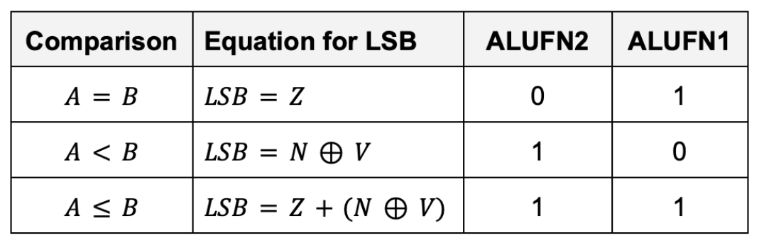
Implement a 32-bit compare unit that generate 1 bit output, depending on the following conditions:
The inputs to the compare unit are:
- The
ALUFNcontrol signals (used to select the comparison to be performed), in particular:ALUFN[2:1] - The
Z,V, andNbits. They’re the output of the adder/subtractor unit. The adder must be in subtraction mode.
Why should the adder be in subtraction mode? Discuss with your team members
Performance
What’s the tpd and tcd of the compare unit?
The Z, V and N inputs to this circuit can only be produced by the adder/subtractor unit. That means we need to first perform a 32-bit addition/subtraction between a and b before we can compare them. This means there’s some significant tpd to produce the output of the compare unit as the RCA is considerably slow.
In real life, you can speed things up considerably by thinking about the relative timing of Z, V and N and then designing your logic to minimize delay paths involving late-arriving signals. For instance, if you need to perform computations involving Z and other variables, you can compute those intermediary output involving the other variables first while “waiting” for Z. We do not need to worry much about it in this Lab as Vivado will do all sorts of optimisation for you.
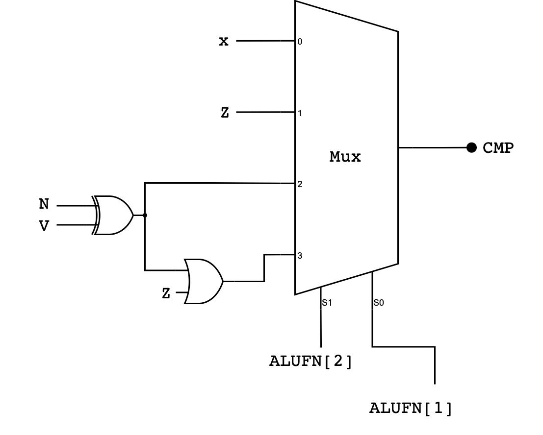
Detailed Compare Unit Schematic
Here’s the detailed schematic of the compare unit. Pay close attention to the bit selector and the corresponding inputs at the MUX:
Implementation Tips
You can use MUX4 created before to implement this:
module MUX4 (
    input s0,
    input s1,
    input [3:0] in,
    output reg out
);

  always @(*) begin
    case ({
      s1, s0
    })
      2'b00:   out = in[0];
      2'b01:   out = in[1];
      2'b10:   out = in[2];
      2'b11:   out = in[3];
      default: out = 0;
    endcase
  end

endmodule
case
Alternatively, you can use case. case is used to select one of several behaviors based on an exact match of a single expression. It is commonly used for opcode or control decoding and maps cleanly to hardware multiplexers.
In Verilog, plain case performs an exact 4-state match, meaning 0, 1, X, and Z are all treated as distinct values. If none of the case items match, the default branch is taken. In combinational logic, you must ensure the output is assigned for all possibilities, typically by including a default.
Example:
always @(*) begin
    case (sel)
        2'b00: y = a;
        2'b01: y = b;
        2'b10: y = c;
        default: y = 0;   // ensures no latch
    endcase
end
Here, sel is evaluated once, one matching branch is chosen, and default guarantees a defined output even for unexpected values.
Test
Expand the cases of this testbench to cover more cases as needed.
`timescale 1ns/1ps

module tb_compare;

  reg  z, v, n;
  reg  [5:0] alufn;
  wire cmp;

  compare dut (
    .z(z),
    .v(v),
    .n(n),
    .alufn(alufn),
    .cmp(cmp)
  );

  // Pack: {z, v, n, sel[1:0], exp_cmp} = 6 bits
  reg [5:0] TEST_CASES [0:7];

  integer i;

  task fail;
    input integer tc;
    input exp;
    begin
      $display("FAIL %0d: exp_cmp=%b got=%b  (z=%b v=%b n=%b alufn=%b)",
               tc, exp, cmp, z, v, n, alufn);
      $finish;
    end
  endtask

  task check_case;
    input integer tc;
    input exp;
    begin
      if (cmp !== exp) fail(tc, exp);
      $display("PASS test case: %0d", tc);
    end
  endtask

  initial begin
    z = 0; v = 0; n = 0; alufn = 0;
    #1;

    // {z, v, n, sel, exp}
    TEST_CASES[0] = {1'b1, 1'b0, 1'b0, 2'b01, 1'b1}; // 1 CMPEQ true
    TEST_CASES[1] = {1'b0, 1'b1, 1'b1, 2'b01, 1'b0}; // 2 CMPEQ false
    TEST_CASES[2] = {1'b0, 1'b0, 1'b1, 2'b10, 1'b1}; // 3 CMPLT true (n^v=1)
    TEST_CASES[3] = {1'b0, 1'b1, 1'b0, 2'b10, 1'b1}; // 4 CMPLT true (overflow flip)
    TEST_CASES[4] = {1'b0, 1'b0, 1'b0, 2'b10, 1'b0}; // 5 CMPLT false
    TEST_CASES[5] = {1'b1, 1'b0, 1'b0, 2'b11, 1'b1}; // 6 CMPLE true via eq
    TEST_CASES[6] = {1'b0, 1'b0, 1'b1, 2'b11, 1'b1}; // 7 CMPLE true via lt
    TEST_CASES[7] = {1'b0, 1'b0, 1'b0, 2'b11, 1'b0}; // 8 CMPLE false

    for (i = 0; i < 8; i = i + 1) begin
      z = TEST_CASES[i][5];
      v = TEST_CASES[i][4];
      n = TEST_CASES[i][3];

      // alufn = {3'b110, sel[1:0], 1'b1}
      alufn = {3'b110, TEST_CASES[i][2:1], 1'b1};

      #1;

      check_case(i+1, TEST_CASES[i][0]);
    end

    $display("ALL PASS");
    $finish;
  end

endmodule
Task 3: Boolean Unit
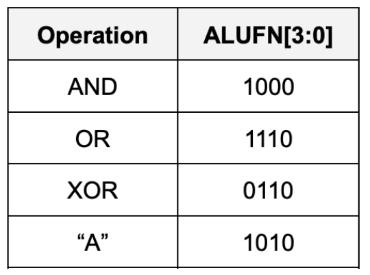
Implement a 32-bit Boolean unit that performs bitwise boolean operation between a and b. The unit should receive 32-bits of a and b as inputs, as well as 4-bit ALUFN[3:0] input, and produce a 32-bit output. In particular it should perform either AND, OR, XOR, or A bitwise boolean operations, depending on the ALUFN signals supplied:
Detailed Boolean Unit Schematic
Here’s the general schematic of the Boolean Unit:
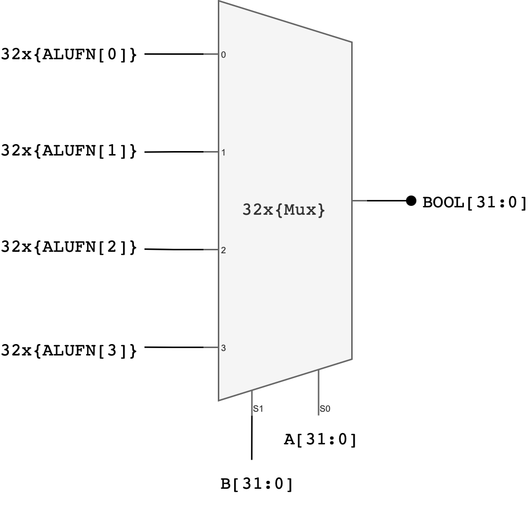
Explanation:
One possible implementation of a 32-bit boolean unit uses 32 copies of a 4-to-1 multiplexer where ALUFN0, ALUFN1, ALUFN2, and ALUFN3 hardcode the operation to be performed, and Ai and Bi are hooked to the multiplexer SELECT inputs. This implementation can produce any of the 16 2-input Boolean functions; but we will only be using 4 of the possibilities: AND, OR, XOR, and A.
In total, you should utilise 32 4-to-1 multiplexers to build the boolean unit. You can utilise the earlier created MUX4.v module to implement this.
Implementation Tips
You can use genvar, generate and for loop to create 32 of these MUX4 modules. Ensure that you connect the pins properly, from lowest to highest bit.
  genvar i;
  generate
    for (i = 0; i < SIZE; i = i + 1) begin : MUXES
      MUX4 u_MUX4 (
          .s0 (...),
          .s1 (...),
          .in (....), // 4 bits, high to low from left to right
          .out(...)
      );
    end
  endgenerate
Test
`timescale 1ns/1ps

module tb_boolean;

  reg  [31:0] a, b;
  reg  [5:0]  alufn;
  wire [31:0] bool_out;

  // DUT (instance name is NOT "boolean")
  boolean u_boolean (
    .a(a),
    .b(b),
    .alufn(alufn),
    .boolean_out(bool_out)
  );

  // {a[31:0], b[31:0], op4[3:0], expected[31:0]}
  reg [99:0] TEST_CASES [0:7];

  integer i;

  task fail;
    input integer tc;
    input [31:0] exp;
    begin
      $display("FAIL %0d: exp=%h got=%h  (a=%h b=%h alufn=%b)",
               tc, exp, bool_out, a, b, alufn);
      $finish;
    end
  endtask

  task check_case;
    input integer tc;
    input [31:0] exp;
    begin
      if (bool_out !== exp)
        fail(tc, exp);
      $display("PASS test case: %0d", tc);
    end
  endtask

  initial begin
    a = 32'd0;
    b = 32'd0;
    alufn = 6'd0;
    #1;

    // {a, b, op4, expected}
    TEST_CASES[0] = {32'hFF00FF00, 32'h0F0F0F0F, 4'b1000, 32'h0F000F00};
    TEST_CASES[1] = {32'hAAAAAAAA, 32'h55555555, 4'b1000, 32'h00000000};
    TEST_CASES[2] = {32'hFF00FF00, 32'h00FF00FF, 4'b1110, 32'hFFFFFFFF};
    TEST_CASES[3] = {32'h12345678, 32'h00000000, 4'b1110, 32'h12345678};
    TEST_CASES[4] = {32'hDEADBEEF, 32'hDEADBEEF, 4'b0110, 32'h00000000};
    TEST_CASES[5] = {32'hAAAAAAAA, 32'h55555555, 4'b0110, 32'hFFFFFFFF};
    TEST_CASES[6] = {32'h12345678, 32'hFFFFFFFF, 4'b1010, 32'h12345678};
    TEST_CASES[7] = {32'h00000000, 32'hDEADBEEF, 4'b1010, 32'h00000000};

    for (i = 0; i < 8; i = i + 1) begin
      a = TEST_CASES[i][99:68];
      b = TEST_CASES[i][67:36];

      // alufn = {2'b01, op4[3:0]}
      alufn = {2'b01, TEST_CASES[i][35:32]};

      #1;

      check_case(i+1, TEST_CASES[i][31:0]);
    end

    $display("ALL PASS");
    $finish;
  end

endmodule
Task 4: Shifter
Implement a 32-bit shifter unit that is able to perform a shift left (SHL), shift right (SHR), or shift right arithmetic (SRA) operation on A:
- The
A[31:0]input supplies the data to be shifted - The low-order 5 bits of the
B[4:0]are used as the shift count (i.e., from 0 to 31 bits of shift) - We do not use the high 27 bits of the
Binput (meaning thatB[31:5]is ignored in this unit)
For example, if A: 0x0000 00F0 and we would like to shift A to the left by FOUR bits, the B input should be 0x0000 0004
The desired operation will be encoded on ALUFN[1:0] as follows:
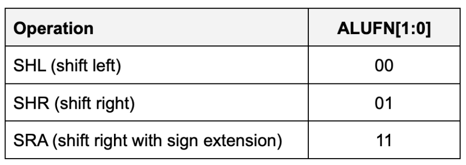
With this encoding, the control signal ALUFN0 controls whether we are performing a left shift or a right shift (SHR). ALUFN1 decides whether we apply the sign extension logic on right shift.
- For
SHLandSHR,0s are shifted into the vacated bit positions. - For
SRA(“shift right arithmetic”), the vacated bit positions are all filled withA31, the sign bit of the original data so that the result will be the same as arithmetically dividing the original data by the appropriate power of 2.
Detailed Shifter Unit Schematic
The simplest implementation is to build three separate shifters: one for shifting left, one for shifting right, and one for shifting right arithmetic.
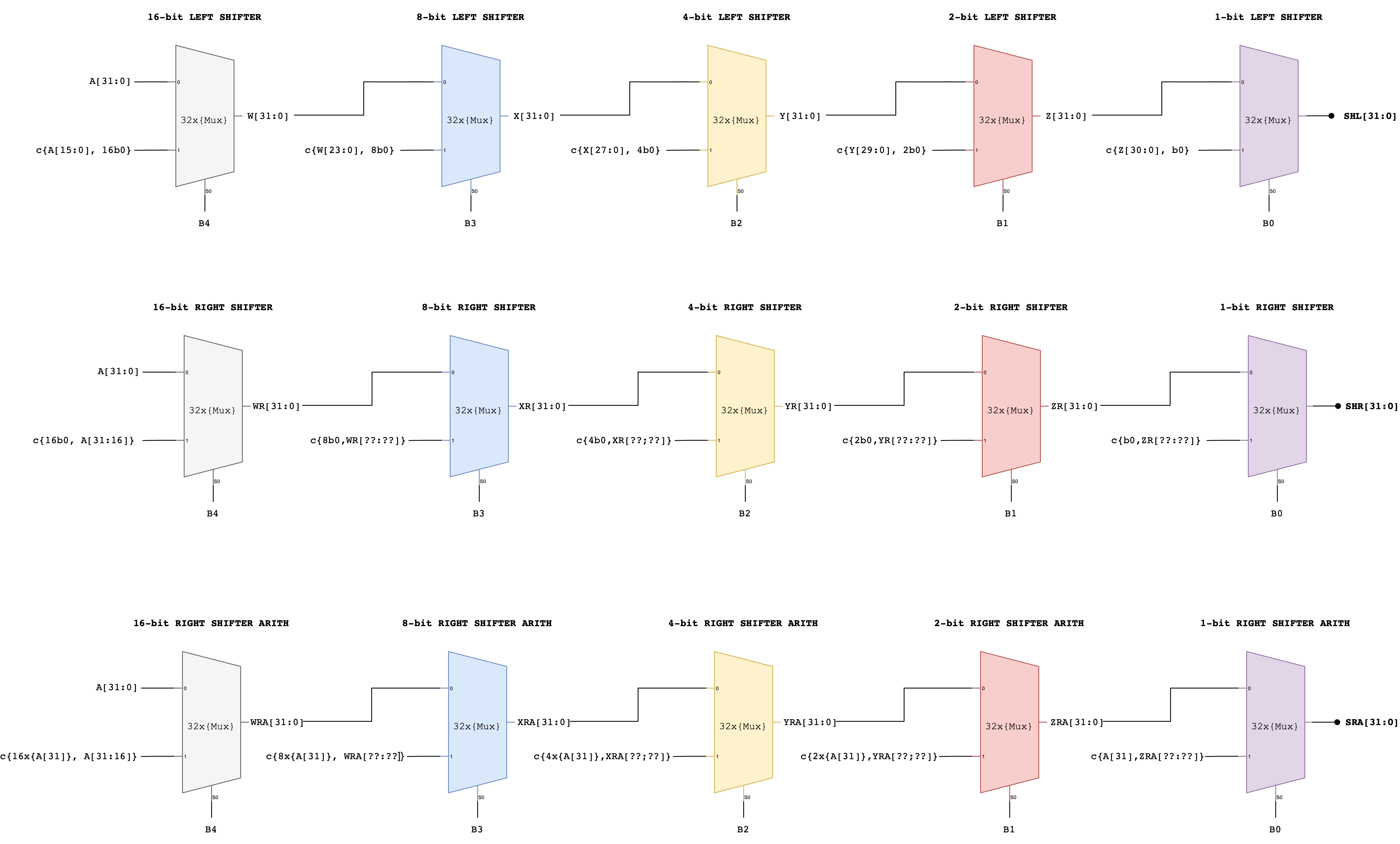
Notice how a multi-bit shift can be accomplished by cascading shifts by various powers of 2.
- For example, a 13-bit shift can be implemented by a shift of 8, followed by a shift of 4, followed by a shift of 1.
- Each shifter unit is just a cascade of multiplexers each controlled by one bit of the shift count.
Afterwards, we can use a 4-way 32-bit multiplexer to select the appropriate answer as the unit’s output.
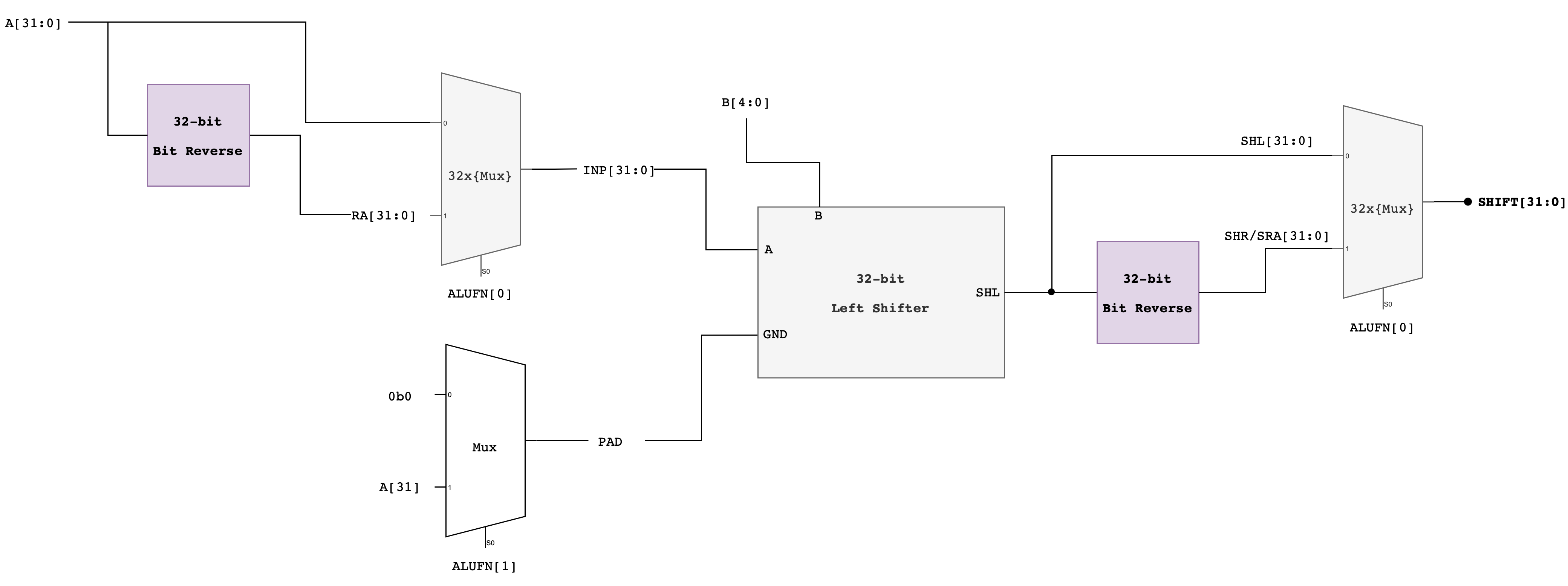
Alternative Approach: Compact Shifter
Another approach that adds latency but saves gates is to use the left shift logic for both left and right shifts, but for right shifts, reverse the bits of the
Ainput first on the way in and reverse the bits of the output on the way out.Here’s the schematic of this compact shifter.
Implementation Tips
You might want to utilise the reverse module below:
module bit_reverse #(
    parameter SIZE = 32
) (
    input  [SIZE-1:0] in,
    output [SIZE-1:0] reversed
);

  genvar i;
  generate
    for (i = 0; i < SIZE; i = i + 1) begin : REV
      assign reversed[i] = in[SIZE-1-i];
    end
  endgenerate

endmodule
Then to build the shifter, assuming you follow the compact shifter approach:
- Make
x_bit_left_shiftermodule that does exactlyxbit shifts if a certain flag is1, wherexis1,2,4,8or16. This is a very simple module, acceptingSHIFTparameter and a flag whether to shift or not to shift, as well asaand thepad(what to fill the empty spaces with). We assume that if it’s used for left-shifting, thenpadwould be0, and if it’s used for SRA, thenpadwould bea31. - Then make a
left_shiftermodule that instantiate 5 of thesex_bit_left_shifterswith varying value ofSHIFT. You should also declare 6 wire connectors of size 32 bits each that connects from the output of the upstream shifter to thed0/d1input of the downstream shifter. - Finally, create
shiftermodule that instantiate aleft_shifter, along with severalbit_reversemodules to determine whether to perform SHL, SRA, or SHR based on the givenalufn.
Test
`timescale 1ns / 1ps
module tb_shifter;

  localparam integer NCASES = 8;

  reg  [31:0] a;
  reg  [ 4:0] b;
  reg  [ 5:0] alufn;
  wire [31:0] shift;

  shifter dut (
      .a(a),
      .b(b),
      .alufn(alufn),
      .shift(shift)
  );

  // Packed test vector: {a[31:0], b_full[31:0], mode[1:0], exp[31:0]} = 98 bits
  reg [97:0] TV[0:NCASES-1];

  integer i;
  integer errors;

  task tick;
    begin
      #1;  // combinational settle
    end
  endtask

  task run_one;
    input integer idx;
    reg [31:0] exp;
    reg [ 1:0] mode;
    reg [31:0] b_full;
    begin
      a      = TV[idx][97:66];
      b_full = TV[idx][65:34];
      mode   = TV[idx][33:32];
      exp    = TV[idx][31:0];

      // shifter takes only 5 bits of b (masked shift amount)
      b      = b_full[4:0];

      // match your encoding: 4'b1000 prefix + 2-bit mode
      alufn  = {4'b1000, mode};

      tick();

      if (shift !== exp) begin
        errors = errors + 1;
        $display("FAIL case %0d: a=%h b_in=%0d(b_full=%0d) mode=%b alufn=%b exp=%h got=%h",
                 idx + 1, a, b, b_full, mode, alufn, exp, shift);
      end else begin
        $display("PASS test case: %0d", idx + 1);
      end
    end
  endtask

  initial begin
    a      = 0;
    b      = 0;
    alufn  = 0;
    errors = 0;

    // Same order as your list (no reverse needed)
    // 1. SHL: simple left shift
    TV[0]  = {32'd1, 32'd1, 2'b00, 32'd2};
    // 2. SHL: overflow bits dropped
    TV[1]  = {32'h80000000, 32'd1, 2'b00, 32'h00000000};
    // 3. SHL: shift amount masked (33 -> 1)
    TV[2]  = {32'd1, 32'd33, 2'b00, 32'd2};
    // 4. SHR: simple logical right shift
    TV[3]  = {32'd8, 32'd2, 2'b01, 32'd2};
    // 5. SHR: negative value zero-filled
    TV[4]  = {32'h80000000, 32'd1, 2'b01, 32'h40000000};
    // 6. SHR: shift amount masked (32 -> 0, no shift)
    TV[5]  = {32'h80000000, 32'd32, 2'b01, 32'h80000000};
    // 7. SRA: arithmetic right shift with sign extend
    TV[6]  = {32'h80000000, 32'd1, 2'b11, 32'hC0000000};
    // 8. SRA: large shift yields all ones
    TV[7]  = {32'h80000000, 32'd31, 2'b11, 32'hFFFFFFFF};

    for (i = 0; i < NCASES; i = i + 1) begin
      run_one(i);
    end

    if (errors == 0) $display("ALL PASS");
    else $display("DONE: %0d failures", errors);

    $finish;
  end

endmodule
Task 5: Multiplier
The multiplier unit performs a multiplication between 32-bit inputs A and B each, and produce a 32-bit output.
Multiplying two 32-bit numbers produces a 64-bit product. However, the result we’re looking for is just the low-order 32-bits of the 64-bit product since our hardware is built to only supports 32-bit outputs.
4-bit Multiplication Logic
It’s hard to imagine a 32-bit multiplier straight up, so let’s scale down to a 4-bit version.
Suppose we want to multiply two 4-bit binary numbers: A = 1011 (which is 11 in decimal) and B = 1101 (which is 13 in decimal).
The multiplication process involves the following steps:
- Write Down the Multiplicands: Write A and B such that each bit of B is aligned under each bit of A.
- Multiply Each Bit of B by A: Multiply each bit of B with the entire number A, shifting the result to the left for each subsequent bit. In binary multiplication, this means we either take A (if the bit in B is 1) or take 0 (if the bit in B is 0).
- Add the Partial Products: Add all the partial products together to get the final result.
    1011   (A = 11 in decimal)
  x 1101   (B = 13 in decimal)
  ------
    1011   (This is A * 1; the rightmost bit in B is 1)
   0000    (This is A * 0; shift left by 1 because we're on the second bit from the right in B)
  1011     (This is A * 1; shift left by 2)
 1011       (This is A * 1; shift left by 3)
------
10001111   (Sum of the above partial products)
Here is a detailed bit-level description of how a 4-bit by 4-bit unsigned multiplication works. This diagram assumes we only want the low-order 4 bits of the 8-bit product.
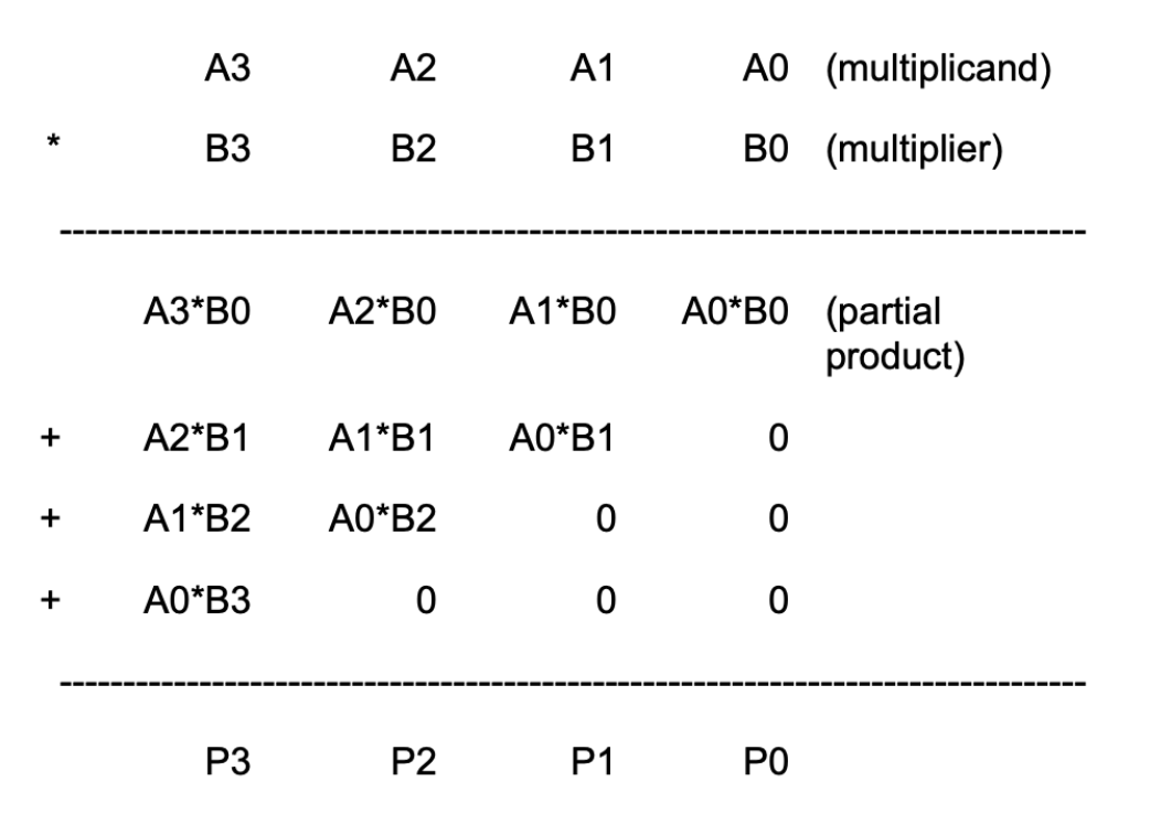
This diagram can be extended in a straightforward way to 32-bit by 32-bit multiplication. Remember that since our machine is only 32-bit, that means we only can store the low-order 32-bits of the result, we don’t need to include the circuitry that generates the rest of the 64-bit product.
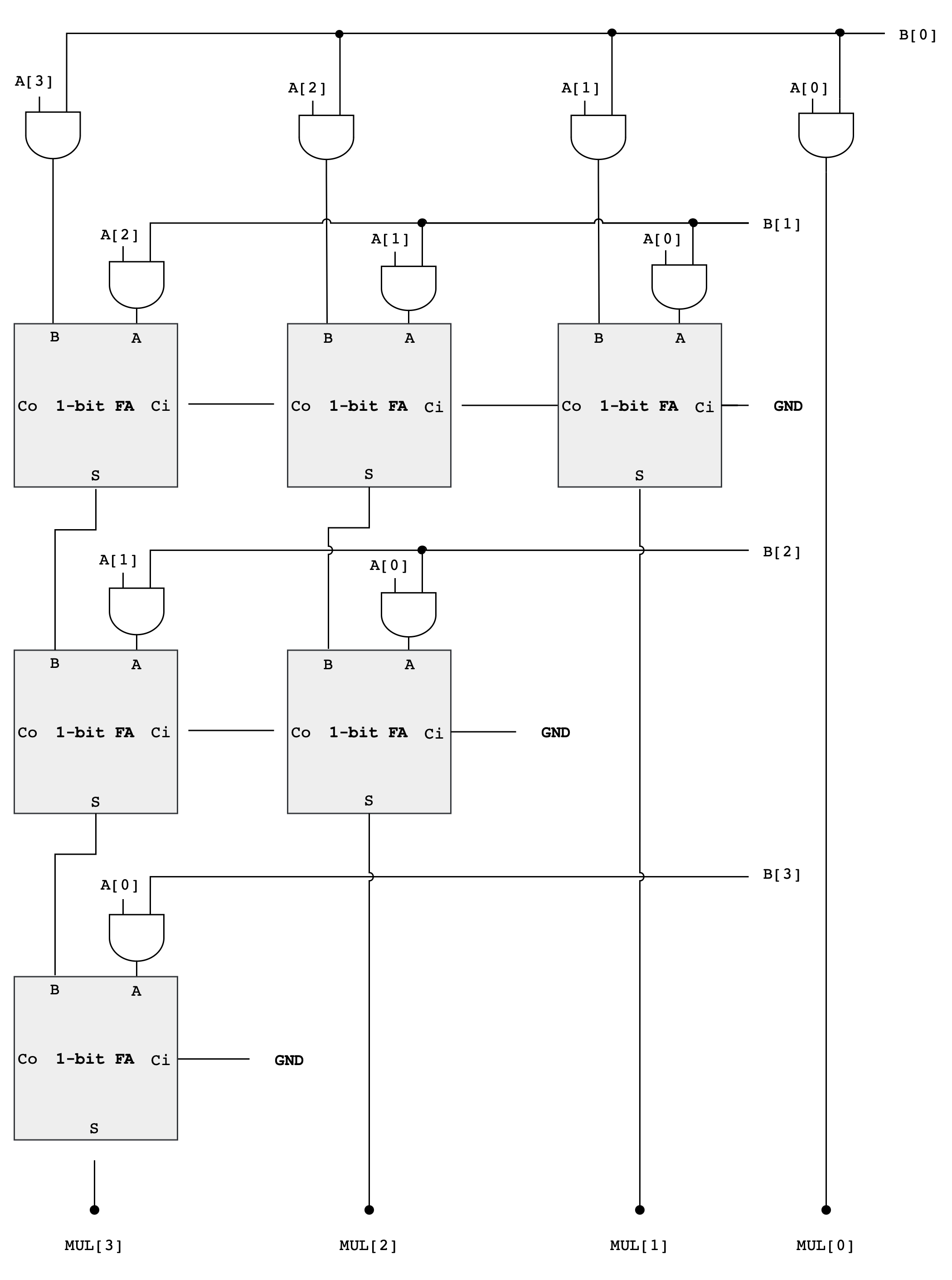
4-bit Multiplier Schematic
As you can see from the diagram above, forming the partial products is easy. Multiplication of two bits can be implemented using an AND gate. The hard and tedious part is adding up all the partial products (there will be 32 partial products in your circuit).
- One can use FA units hooked up in a ripple-carry configuration to add each partial product to the accumulated sum of the previous partial products (see the diagram below)
- The circuit closely follows the diagram above but omits an FA module if two of its inputs are
0
Multiplier Analysis
The circuit above works with both unsigned operands and signed two’s complement operands.
Why do we ignore the MSB of the operands?
This may seem strange, don’t we have to worry about the most significant bit (MSB) of the operands? With unsigned operands the MSB has a weight of \(2^{MSB}\) (assuming the bits are numbered 0 to MSB) but with signed operands the MSB has a weight of \(-2^{MSB}\).
Doesn’t our circuitry need to take that into account?
Turns out it does, but when we are only saving the lower half of the product, the differences don’t appear. The multiplicand (A in the figure above) can be either unsigned or two’s complement (signed), and the FA circuits will perform correctly in either case.
When the multiplier (B in the figure above) is signed, we should subtract the final partial product instead of adding it.
- But subtraction is the same as adding the negative, and the negative of a two’s complement number can be computed by taking its complement and adding 1.
- When we work this through we see that the low-order bit of the partial product is the same whether positive or negated.
The low-order bit is ALL that we need when saving only the lower half of the product.
If we were building a multiplier that computed the full product, we’d see many differences between a multiplier that handles unsigned operands and one that handles two’s complement (signed) operands, but these differences only affect how the high half of the product is computed.
Example: 4-bit Signed Multiplication
Let’s use a 4-bit example to illustrate why the lower half of the product is the same whether we are dealing with signed or unsigned numbers, especially in the context of two’s complement arithmetic.
Suppose we have A = 0110 (6 in decimal) multiplied by B = 1101 (-3 in decimal, two’s complement).
As Unsigned Numbers, they are:
A = 0110(6 in decimal)B = 1101(13 in decimal, treated as unsigned)
The multiplication (ignoring overflow) of these two numbers is:
   0110   (A = 6)
 x 1101   (B = 13, as unsigned)
 ------
   0110   (A * 1)
  0000    (A * 0, shift left by 1)
 0110     (A * 1, shift left by 2)
0110      (A * 1, shift left by 3)
------
1001110   (78 in decimal, unsigned)
However, the multiplication as signed numbers works differently because the last partial product should be negated:
    0110   (A = 6)
  x 1101   (B = -3, as signed)
  ------
    0110   (A * 1)
   0000    (A * 0, shift left by 1)
  0110     (A * 1, shift left by 2)
 1010000   (A * 1, shift left by 3, we get 0110000 but it should be negated, resulting in 1010000)
------
 1101110 (-18 in decimal, signed)
The negation of
0110000is1010000(flip the bits, then add 1).
In both cases, the lower half of the product (1110) is the same. This is because the difference caused by the negative MSB in the two’s complement representation affects only the higher-order bits, which are outside the lower half of the product.
When multiplying two numbers where the sign of one is significant (like in two’s complement), the alterations to the upper bits due to the sign are not reflected in the lower bits. This is why, in certain computational scenarios where only the lower half of the product is of interest, the circuitry can be simplified as it doesn’t need to differentiate between signed and unsigned numbers.
Design Note
Combinational multipliers implemented as described above are pretty slow! There are many design tricks we can use to speed things up – see the appendix on “Computer Arithmetic” in any of the editions of Computer Architecture: A Quantitative Approach by John Hennessy and David Patterson (Morgan Kauffmann publishers).
Implementation Notes
This design is likely going to take a long time to simulate. That’s normal.
Verilog Function
When a design contains hundreds of repeated primitives, Verilog encourages you to separate structure from indexing. Instead of instantiating modules inline with deeply nested generate loops, one common pattern is to allocate large, flat vectors of wires and then carefully map each logical connection into an index of those vectors.
A key syntax feature that enables this is the Verilog function used for constant computation:
function integer f;
  input integer i;
  begin
    f = /* expression involving i */;
  end
endfunction
When such a function is called from a localparam, it is evaluated at elaboration time, not during simulation. This allows you to compute indices, offsets, or sizes symbolically, while still producing static hardware. The important constraint is that everything inside the function must be resolvable from constants, parameters, or generate indices.
module example #(
    parameter N = 8
);

  // Function used only for constant computation
  function integer base_index;
    input integer row;
    integer k;
    integer acc;
    begin
      acc = 0;
      for (k = 0; k < row; k = k + 1) begin
        acc = acc + (N - k);
      end
      base_index = acc;
    end
  endfunction

  genvar i;
  generate
    for (i = 0; i < N; i = i + 1) begin : GEN_ROWS
      // Evaluated at elaboration time
      localparam integer BASE = base_index(i);

      wire [3:0] w;
      // BASE is a constant within this generate block
      // and can be safely used for indexing or sizing
    end
  endgenerate

endmodule
In this pattern, the function base_index is never executed during simulation. It is evaluated by the compiler when elaborating the design, and the result is baked into each localparam. Because of that, the function body may only depend on constants, parameters, or generate indices, never on runtime signals.
localparam
Another useful construct to know when building the multiplier is localparam. Unlike parameter, a localparam cannot be overridden from outside the module, which makes it suitable for internal bookkeeping such as base indices or widths derived from other parameters. Using localparam inside a generate block lets each generated instance carry its own constant values without duplicating code.
module example #(
    parameter N = 8
);

  genvar i;
  generate
    for (i = 0; i < N; i = i + 1) begin : GEN
      // Per-instance constant, derived from parameters and genvar
      localparam integer WIDTH = N - i;
      localparam integer BASE  = i * 4;

      wire [WIDTH-1:0] slice;

      // WIDTH and BASE are fixed constants for this instance
      // and cannot be overridden from outside the module
    end
  endgenerate

endmodule
Each iteration of the generate loop gets its own copy of WIDTH and BASE, computed at elaboration time. Because they are declared as localparam, they are guaranteed to remain internal to the module and are safe to use for indexing, sizing, or offsets when building large regular structures.
Nested generate
generate blocks can be nested, and that each for loop has its own genvar.
Nested generate loops are elaborated hierarchically, producing a grid of hardware instances whose indices are known at compile time. The naming of generate blocks is what keeps these hierarchies manageable and debuggable.
Here is a small example that demonstrates both ideas without committing to any specific algorithm.
module example (
    input  [3:0] a,
    input  [3:0] b,
    output [3:0] y
);

  // Flat arrays of wires for many identical primitives
  wire [3:0] in0;
  wire [3:0] in1;
  wire [3:0] out;

  // -------------------------------------------------
  // Phase 1: instantiate all primitive components
  // -------------------------------------------------
  genvar i;
  generate
    for (i = 0; i < 4; i = i + 1) begin : GEN_PRIMS
      and_gate u_and (
          .a (in0[i]),
          .b (in1[i]),
          .y (out[i])
      );
    end
  endgenerate

  // -------------------------------------------------
  // Phase 2: wire up the primitives
  // -------------------------------------------------
  genvar r, c;
  generate
    for (r = 0; r < 4; r = r + 1) begin : GEN_WIRING
      // hierarchical name: GEN_WIRING[r].GEN_BITS[c]
      for (c = 0; c < 1; c = c + 1) begin : GEN_BITS
        assign in0[r] = a[r];
        assign in1[r] = b[r];
        assign y[r]   = out[r];
      end
    end
  endgenerate

endmodule
The outer and inner generate blocks form a clear hierarchy (GEN_WIRING[r].GEN_BITS[c]) that the simulator and synthesis tools preserve. Each loop index is a compile-time constant, so every instance and connection is fixed at elaboration.
By separating instantiation from wiring, the code reads like a static schematic: first you declare all the components, then you describe how they are connected. This style scales well when the number of primitives grows large, because the structure stays regular and debuggable.
Test
`timescale 1ns/1ps

module tb_multiplier;

  // DUT ports
  reg  [31:0] a;
  reg  [31:0] b;
  wire [31:0] mul;

  // DUT
  multiplier dut (
    .a(a),
    .b(b),
    .mul(mul)
  );

  // Simple "tick" (since DUT is combinational, just let signals settle)
  task tick;
    begin
      #1;
    end
  endtask

  // Check one test case
  task check_case;
    input integer idx;
    input [31:0] in_a;
    input [31:0] in_b;
    input [31:0] exp_mul;
    begin
      a = in_a;
      b = in_b;
      tick();

      if (mul !== exp_mul) begin
        $display("FAIL case %0d", idx);
        $display("  a   = 0x%08h (%0d)", a, $signed(a));
        $display("  b   = 0x%08h (%0d)", b, $signed(b));
        $display("  exp = 0x%08h (%0d)", exp_mul, $signed(exp_mul));
        $display("  got = 0x%08h (%0d)", mul, $signed(mul));
        $finish;
      end else begin
        $display("PASS case %0d", idx);
      end
    end
  endtask

  // [95:64]=a, [63:32]=b, [31:0]=expected
  reg [95:0] VEC [0:7];
  integer i;

  initial begin
    // 1. small positive multiply
    VEC[0] = {32'd3,            32'd4,            32'd12};

    // 2. multiply by zero
    VEC[1] = {32'd12345,        32'd0,            32'd0};

    // 3. negative times positive
    VEC[2] = {-32'sd7,        32'd6,            -32'sd42};

    // 4. negative times negative
    VEC[3] = {-32'sd8,        -32'sd5,        32'd40};

    // 5. large values with truncation (lower 32 bits kept)
    VEC[4] = {32'hFFFFFFFF,     32'd2,            32'hFFFFFFFE};

    // 6. sign bit interaction
    VEC[5] = {32'h80000000,     32'd2,            32'h00000000};

    // 7. power-of-two scaling
    VEC[6] = {32'd1024,         32'd1024,         32'd1048576};

    // 8. overflow wraps around
    VEC[7] = {32'h7FFFFFFF,     32'd2,            32'hFFFFFFFE};

    // Run tests
    for (i = 0; i < 8; i = i + 1) begin
      check_case(i+1, VEC[i][95:64], VEC[i][63:32], VEC[i][31:0]);
    end

    $display("ALL PASS");
    $finish;
  end

endmodule
Task 6: Assembling the ALU
You are free to implement each module in whichever way you deem fit, or even come up with a new schematic as long as you don’t use Lucid’s math operators and compare operators to implement any of these 13 functionalities. You can however use them for indexing purposes or conditional loops.
Create a new file alu.v and assemble the outputs of the finished adder, multiplier, compare, boolean and shift units to produce 32-bit alu output based on the input ALUFN signal. The simplest approach is to use a 4-way 32-bit multiplexer as shown in the schematic below:
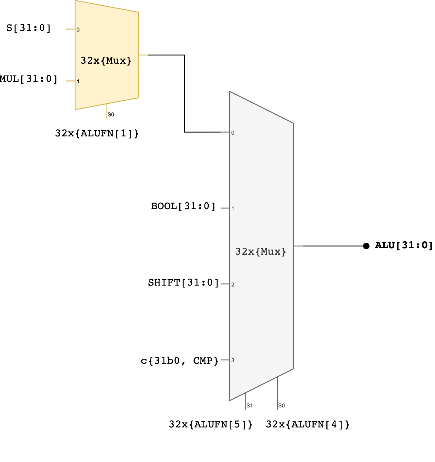
You can use MUX4, or use the case statement, or use plain if-else statements to implement this.
Two control signals (ALUFN[5:4]) that we have never used before in the individual module have now been utilised to select which unit will supply the value for the ALU output. The encodings for ALUFN[5:0] should follow this table that you’ve seen in the beginning of this handout:
Note that the Z, V, and N signals from the adder/subtractor unit are included in the terminal list for the alu subcircuit (they’re counted as ALU’s output). Please connect these terminals properly in your alu.v file.
Test
Here’s a simple tester to get you started. We only test one case for each ALUFN, which is certainly not enough. Expand the test cases on your own.
`timescale 1ns/1ps

module tb_alu;

  reg  [31:0] a;
  reg  [31:0] b;
  reg  [5:0]  alufn;
  wire [31:0] out;
  wire        z, v, n;

  alu dut (
    .a(a),
    .b(b),
    .alufn(alufn),
    .out(out),
    .z(z),
    .v(v),
    .n(n)
  );

  task tick;
    begin
      #1;
    end
  endtask

  task check;
    input integer idx;
    input [31:0] exp_out;
    input exp_z, exp_v, exp_n;
    begin
      tick();
      if (out !== exp_out || z !== exp_z || v !== exp_v || n !== exp_n) begin
        $display("FAIL case %0d", idx);
        $display("  a=%h b=%h alufn=%h", a, b, alufn);
        $display("  exp_out=%h got_out=%h", exp_out, out);
        $display("  exp_z=%b got_z=%b exp_v=%b got_v=%b exp_n=%b got_n=%b",
                 exp_z, z, exp_v, v, exp_n, n);
        $finish;
      end else begin
        $display("PASS case %0d", idx);
      end
    end
  endtask

  initial begin
    // 00 ADD 0 + 0
    a = 32'd0; b = 32'd0; alufn = 6'h00;
    check(1, 32'd0, 1'b1, 1'b0, 1'b0);

    // 01 ADD pos overflow
    a = 32'h7FFFFFFF; b = 32'd1; alufn = 6'h00;
    check(2, 32'h80000000, 1'b0, 1'b1, 1'b1);

    // 02 SUB 7 - 5
    a = 32'd7; b = 32'd5; alufn = 6'h01;
    check(3, 32'd2, 1'b0, 1'b0, 1'b0);

    // 03 SUB neg overflow
    a = 32'h80000000; b = 32'd1; alufn = 6'h01;
    check(4, 32'h7FFFFFFF, 1'b0, 1'b1, 1'b0);

    // 04 MUL 3 * 4
    a = 32'd3; b = 32'd4; alufn = 6'h02;
    check(5, 32'd12, 1'b0, 1'b0, 1'b0);

    // 05 MUL 80000000 * 2
    a = 32'h80000000; b = 32'd2; alufn = 6'h02;
    check(6, 32'd0, 1'b0, 1'b0, 1'b1);

    // 06 AND
    a = 32'hF0F0F0F0; b = 32'h0F0F0F0F; alufn = 6'h18;
    check(7, 32'h00000000, 1'b0, 1'b0, 1'b1);

    // 07 OR
    a = 32'hF0F0F0F0; b = 32'h0F0F0F0F; alufn = 6'h1E;
    check(8, 32'hFFFFFFFF, 1'b0, 1'b0, 1'b1);

    // 08 XOR
    a = 32'hAAAA5555; b = 32'hFFFF0000; alufn = 6'h16;
    check(9, 32'h55555555, 1'b0, 1'b0, 1'b1);

    // 09 PASSA
    a = 32'd5; b = 32'd7; alufn = 6'h1A;
    check(10, 32'd5, 1'b0, 1'b0, 1'b0);

    // 10 SHL
    a = 32'd1; b = 32'd3; alufn = 6'h20;
    check(11, 32'd8, 1'b0, 1'b0, 1'b0);

    // 11 SHR
    a = 32'd16; b = 32'd1; alufn = 6'h21;
    check(12, 32'd8, 1'b0, 1'b0, 1'b0);

    // 12 SRA
    a = 32'h80000000; b = 32'd1; alufn = 6'h23;
    check(13, 32'hC0000000, 1'b0, 1'b1, 1'b0);

    // 13 CMPEQ
    a = 32'd5; b = 32'd5; alufn = 6'h33;
    check(14, 32'd1, 1'b1, 1'b0, 1'b0);

    // 14 CMPLT
    a = 32'd3; b = 32'd7; alufn = 6'h35;
    check(15, 32'd1, 1'b0, 1'b0, 1'b1);

    // 15 CMPLE
    a = 32'd5; b = 32'd5; alufn = 6'h37;
    check(16, 32'd1, 1'b1, 1'b0, 1'b0);

    $display("ALL PASS");
    $finish;
  end

endmodule
Better ALU Tester
Automated ALU Tester
You can create pipelined ALU (put dffs / regs at the A, B, and ALUFN ports, and also output ports: alu out, z, v, and n) like you did for your pipelined RCA, and reused 90% of the code created for your automated RCA tester to create the equivalent one for your ALU.
Similar to what you did for the RCA in the previous lab, we can create a datapath + control unit (FSM) for the automated ALU tester. This is a ROM that you can use:
`timescale 1ns / 1ps

module alu_testcase_rom #(
    parameter ADDR_W = 5  // enough for 16+ cases
) (
    input      [ADDR_W-1:0] addr,
    output reg [      31:0] a,
    output reg [      31:0] b,
    output reg [       5:0] alufn,
    output reg [      31:0] exp_out,
    output reg              exp_z,
    output reg              exp_v,
    output reg              exp_n
);

  always @(*) begin
    // defaults
    a       = 32'b0;
    b       = 32'b0;
    alufn   = 6'b0;
    exp_out = 32'b0;
    exp_z   = 1'b0;
    exp_v   = 1'b0;
    exp_n   = 1'b0;

    case (addr)

      // ---- ADD ----
      5'd0: begin  // ADD 0 + 0
        a = 32'd0;
        b = 32'd0;
        alufn = 6'h00;
        exp_out = 32'd0;
        exp_z = 1'b1;
        exp_v = 1'b0;
        exp_n = 1'b0;
      end

      5'd1: begin  // ADD pos overflow
        a = 32'h7FFFFFFF;
        b = 32'd1;
        alufn = 6'h00;
        exp_out = 32'h80000000;
        exp_z = 1'b0;
        exp_v = 1'b1;
        exp_n = 1'b1;
      end

      // ---- SUB ----
      5'd2: begin  // SUB 7 - 5
        a = 32'd7;
        b = 32'd5;
        alufn = 6'h01;
        exp_out = 32'd2;
        exp_z = 1'b0;
        exp_v = 1'b0;
        exp_n = 1'b0;
      end

      5'd3: begin  // SUB neg overflow
        a = 32'h80000000;
        b = 32'd1;
        alufn = 6'h01;
        exp_out = 32'h7FFFFFFF;
        exp_z = 1'b0;
        exp_v = 1'b1;
        exp_n = 1'b0;
      end

      // ---- MUL ----
      5'd4: begin  // MUL 3 * 4
        a = 32'd3;
        b = 32'd4;
        alufn = 6'h02;
        exp_out = 32'd12;
        exp_z = 1'b0;
        exp_v = 1'b0;
        exp_n = 1'b0;
      end

      5'd5: begin  // MUL 0x80000000 * 2
        a = 32'h80000000;
        b = 32'd2;
        alufn = 6'h02;
        exp_out = 32'd0;
        exp_z = 1'b0;
        exp_v = 1'b0;
        exp_n = 1'b1;
      end

      // ---- BOOLEAN ----
      5'd6: begin  // AND
        a = 32'hF0F0F0F0;
        b = 32'h0F0F0F0F;
        alufn = 6'h18;
        exp_out = 32'h00000000;
        exp_z = 1'b0;
        exp_v = 1'b0;
        exp_n = 1'b1;
      end

      5'd7: begin  // OR
        a = 32'hF0F0F0F0;
        b = 32'h0F0F0F0F;
        alufn = 6'h1E;
        exp_out = 32'hFFFFFFFF;
        exp_z = 1'b0;
        exp_v = 1'b0;
        exp_n = 1'b1;
      end

      5'd8: begin  // XOR
        a = 32'hAAAA5555;
        b = 32'hFFFF0000;
        alufn = 6'h16;
        exp_out = 32'h55555555;
        exp_z = 1'b0;
        exp_v = 1'b0;
        exp_n = 1'b1;
      end

      5'd9: begin  // PASSA
        a = 32'd5;
        b = 32'd7;
        alufn = 6'h1A;
        exp_out = 32'd5;
        exp_z = 1'b0;
        exp_v = 1'b0;
        exp_n = 1'b0;
      end

      // ---- SHIFTS ----
      5'd10: begin  // SHL
        a = 32'd1;
        b = 32'd3;
        alufn = 6'h20;
        exp_out = 32'd8;
        exp_z = 1'b0;
        exp_v = 1'b0;
        exp_n = 1'b0;
      end

      5'd11: begin  // SHR
        a = 32'd16;
        b = 32'd1;
        alufn = 6'h21;
        exp_out = 32'd8;
        exp_z = 1'b0;
        exp_v = 1'b0;
        exp_n = 1'b0;
      end

      5'd12: begin  // SRA
        a = 32'h80000000;
        b = 32'd1;
        alufn = 6'h23;
        exp_out = 32'hC0000000;
        exp_z = 1'b0;
        exp_v = 1'b1;
        exp_n = 1'b0;
      end

      // ---- COMPARE ----
      5'd13: begin  // CMPEQ
        a = 32'd5;
        b = 32'd5;
        alufn = 6'h33;
        exp_out = 32'd1;
        exp_z = 1'b1;
        exp_v = 1'b0;
        exp_n = 1'b0;
      end

      5'd14: begin  // CMPLT
        a = 32'd3;
        b = 32'd7;
        alufn = 6'h35;
        exp_out = 32'd1;
        exp_z = 1'b0;
        exp_v = 1'b0;
        exp_n = 1'b1;
      end

      5'd15: begin  // CMPLE
        a = 32'd5;
        b = 32'd5;
        alufn = 6'h37;
        exp_out = 32'd1;
        exp_z = 1'b1;
        exp_v = 1'b0;
        exp_n = 1'b0;
      end

      default: begin
      end
    endcase
  end

endmodule
Assuming you have the top module of this automated ALU tester as follows:
module alu_selftest_top #(
    parameter SIZE   = 32,
    parameter ADDR_W = 5,
    parameter STAGES = 3
) (
    input wire clk,
    input wire rst,
    input wire start,
    input wire force_error,

    output wire running_signal,
    output wire error_signal,

    output wire [ADDR_W-1:0] index_out,
    output wire [  SIZE-1:0] dut_alu_out,
    output wire [  SIZE-1:0] expected_alu_out
);
You can use the following testbench:
`timescale 1ns / 1ps

module tb_alu_selftest_top;

  localparam SIZE = 32;
  localparam ADDR_W = 4;
  localparam STAGES = 2;

  reg clk;
  reg rst;
  reg start;
  reg force_error;

  wire running_signal;
  wire error_signal;

  wire [ADDR_W-1:0] index_out;
  wire [SIZE-1:0] dut_alu_out;
  wire [SIZE-1:0] expected_alu_out;

  // DUT: self-test top
  alu_selftest_top #(
      .SIZE  (SIZE),
      .ADDR_W(ADDR_W),
      .STAGES(STAGES)
  ) dut (
      .clk(clk),
      .rst(rst),
      .start(start),
      .force_error(force_error),
      .running_signal(running_signal),
      .error_signal(error_signal),
      .index_out(index_out),
      .dut_alu_out(dut_alu_out),
      .expected_alu_out(expected_alu_out)
  );

  // clock: 100 MHz (10 ns period)
  initial begin
    clk = 1'b0;
    forever #5 clk = ~clk;
  end

  // helper: wait N rising edges
  task wait_cycles;
    input integer n;
    integer k;
    begin
      for (k = 0; k < n; k = k + 1) @(posedge clk);
    end
  endtask

  // main stimulus
  initial begin
    $dumpfile("tb_alu_selftest_top.vcd");
    $dumpvars(0, tb_alu_selftest_top);

    // defaults
    rst = 1'b1;
    start = 1'b0;
    force_error = 1'b0;

    // reset
    wait_cycles(2);
    rst = 1'b0;

    // start pulse (1 cycle)
    @(negedge clk);
    start = 1'b1;
    @(negedge clk);
    start = 1'b0;

    while (index_out !== {ADDR_W{1'b1}}) begin
      // wait for completion
      wait_cycles(4);
      // report
      if (error_signal === 1'b0) begin
        $display("SELFTEST addr = %0d PASS at time %0t", index_out, $time);
      end else begin
        $display("SELFTEST FAIL at time %0t", $time);
        $display("  fail_addr = %0d (0x%0h)", index_out, index_out);
        $display("  got  : s=0x%0h", dut_alu_out);
        $display("  exp  : s=0x%0h", expected_alu_out);
        $finish;
      end
    end
    $display("PASS: Pass all test cases.")
    $finish;
  end

  // safety timeout
  initial begin
    #5000;
    $display("TIMEOUT: done never asserted.");
    $finish;
  end

endmodule
Manual ALU Tester
For this part, you should assume that you will receive inputs of a, b, and alufn, and some button presses (conditioned) to latch the values and move forward/display the result. You can implement it using a simple FSM to achieve something like this:
Assuming you have pipelined ALU to begin with, you can use the following template:
We use the register and edge_detector module from the previous labs.
// ============================================================
// Manual ALU Tester
// Fill the ____ / TODO blocks only.
// Do not change the interface.
// ============================================================

module manual_tester_alu (
    input         clk,
    input         rst,
    input  [24:0] io_dip, // flattened io_dip from alchitry_top
    input  [4:0]  io_button, // assume signal is conditioned
    output [34:0] alu_out,
    output [7:0]  state_indicator
);

  // ----------------------------
  // Registers / wires (given)
  // ----------------------------
  wire [31:0] a_q;
  wire [31:0] b_q;
  wire [5:0]  alufn_q;
  wire [34:0] alu_out_q;

  wire [31:0] u_alu_out;
  wire        u_z_out;
  wire        u_v_out;
  wire        u_n_out;

  // ----------------------------
  // Enable
  // ----------------------------
  wire en;
  assign en = 1'b1;

  // ----------------------------
  // Instantiate pipelined_alu (fill)
  // ----------------------------
  pipelined_alu u_alu (
      .clk  (_____________),
      .rst  (_____________),
      .en   (_____________),
      .a    (_____________),
      .b    (_____________),
      .alufn(_____________),
      .out  (_____________),
      .z    (_____________),
      .v    (_____________),
      .n    (_____________)
  );

  // ----------------------------
  // Next-state regs (given)
  // ----------------------------
  reg [31:0] a_d;
  reg [31:0] b_d;
  reg [5:0]  alufn_d;
  reg [34:0] alu_out_d;

  // ----------------------------
  // Register instances (fill)
  // ----------------------------
  register #(.W(32)) u_reg_a (
      .clk(______), .rst(______), .en(______), .d(______), .q(______)
  );

  register #(.W(32)) u_reg_b (
      .clk(______), .rst(______), .en(______), .d(______), .q(______)
  );

  register #(.W(6)) u_reg_alufn (
      .clk(______), .rst(______), .en(______), .d(______), .q(______)
  );

  register #(.W(35)) u_reg_alu_out (
      .clk(______), .rst(______), .en(______), .d(______), .q(______)
  );

  // ----------------------------
  // FSM constants (fill)
  // ----------------------------
  localparam NUM_STATES   = ______;                // TODO: how many states?
  localparam STATES_WIDTH = $clog2(NUM_STATES);

  localparam S_STORE_LOWER_A  = ______;
  localparam S_STORE_HIGHER_A = ______;
  localparam S_STORE_LOWER_B  = ______;
  localparam S_STORE_HIGHER_B = ______;
  localparam S_STORE_ALUFN    = ______;
  localparam S_COMPUTE        = ______;
  localparam S_RESET          = ______;

  // ----------------------------
  // State register (fill W and connections)
  // ----------------------------
  reg  [STATES_WIDTH-1:0] state_d;
  wire [STATES_WIDTH-1:0] state_q;

  register #(.W(______)) u_reg_state (
      .clk(______), .rst(______), .en(______), .d(______), .q(______)
  );

  // ----------------------------
  // Edge detector (fill)
  // ----------------------------
  wire next_edge_rise;

  edge_detector u_edge_detector (
      .clk  (______),                 // TODO
      .rst  (______),                 // TODO
      .sig  (______),                 // TODO: which button bit?
      .pulse(______)                  // TODO
  );

  // ----------------------------
  // FSM combinational logic (fill the TODO lines)
  // ----------------------------
  always @(*) begin
    // defaults (fill)
    state_d   = _______________________;
    alu_out_d = _______________________;
    a_d       = _______________________;
    b_d       = _______________________;
    alufn_d   = _______________________;

    case (state_q)

      S_STORE_LOWER_A: begin
        // TODO: load lower 16 bits of A from io_dip[15:0]
        a_d = _______________________________________________;
        if (next_edge_rise) state_d = _______________________;
      end

      S_STORE_HIGHER_A: begin
        // TODO: load upper 16 bits of A from io_dip[15:0]
        a_d = _______________________________________________;
        if (next_edge_rise) state_d = _______________________;
      end

      S_STORE_LOWER_B: begin
        // TODO: load lower 16 bits of B from io_dip[15:0]
        b_d = _______________________________________________;
        if (next_edge_rise) state_d = _______________________;
      end

      S_STORE_HIGHER_B: begin
        // TODO: load upper 16 bits of B from io_dip[15:0]
        b_d = _______________________________________________;
        if (next_edge_rise) state_d = _______________________;
      end

      S_STORE_ALUFN: begin
        // TODO: load ALUFN (6 bits) from switches (suggested: io_dip[21:16])
        alufn_d = ____________________________________________;
        if (next_edge_rise) state_d = _______________________;
      end

      S_COMPUTE: begin
        // TODO: pack flags + result into alu_out_d
        // format: {z, v, n, out[31:0]} => 35 bits
        alu_out_d = __________________________________________;
        if (next_edge_rise) state_d = _______________________;
      end

      S_RESET: begin
        // TODO: clear output register
        alu_out_d = __________________________________________;
        if (next_edge_rise) state_d = _______________________;
      end

      default: begin
        state_d = _______________________; // TODO: safe default
      end
    endcase
  end

  // ----------------------------
  // Outputs (fill if needed)
  // ----------------------------
  assign alu_out = ___________________________________;       // TODO: map to alu_out_q
  assign state_indicator = ____________________________;       // TODO: map to state_q (zero-extend if needed)

endmodule
Then you can use the following testbench:
`timescale 1ns / 1ps

// Minimal Verilog-2005 TB: drive DIP + button pulses, dump waveforms.
// No self-checks. Just step through: store A low/high, store B low/high, store alufn, compute, reset.

module tb_manual_tester_alu;

  reg         clk;
  reg         rst;
  reg  [24:0] io_dip;
  reg  [ 4:0] io_button;
  wire [34:0] alu_out;
  wire [ 7:0] state_indicator;

  manual_tester_alu dut (
      .clk(clk),
      .rst(rst),
      .io_dip(io_dip),
      .io_button(io_button),
      .alu_out(alu_out),
      .state_indicator(state_indicator)
  );

  // clock
  initial begin
    clk = 1'b0;
    forever #5 clk = ~clk;  // 10ns period
  end

  // waveform dump
  initial begin
    $dumpfile("tb_manual_tester_alu.vcd");
    $dumpvars(0, tb_manual_tester_alu);
  end

  task wait_cycles;
    input integer n;
    integer i;
    begin
      for (i = 0; i < n; i = i + 1) @(posedge clk);
    end
  endtask

  // pulse io_button[0] to advance state (edge_detector sees rising edge)
  task next;
    begin
      io_button[0] = 1'b0;
      @(posedge clk);
      io_button[0] = 1'b1;
      @(posedge clk);
      io_button[0] = 1'b0;
      @(posedge clk);
    end
  endtask

  // set DIP lower 16 bits
  task dip16;
    input [15:0] v;
    begin
      io_dip[15:0] = v;
    end
  endtask

  // set DIP alufn field [21:16]
  task dip_alufn;
    input [5:0] fn;
    begin
      io_dip[21:16] = fn;
    end
  endtask

  initial begin
    // init
    rst = 1'b1;
    io_dip = 25'b0;
    io_button = 5'b0;

    wait_cycles(2);
    rst = 1'b0;
    wait_cycles(2);

    // Example transaction:
    // A = 0x12345678
    // B = 0x9ABCDEF0
    // alufn = 0x08 (pick whatever your ALU expects)
    //
    // Sequence should be:
    //   STORE_LOWER_A  (dip16 = A[15:0])  -> next
    //   STORE_HIGHER_A (dip16 = A[31:16]) -> next
    //   STORE_LOWER_B  (dip16 = B[15:0])  -> next
    //   STORE_HIGHER_B (dip16 = B[31:16]) -> next
    //   STORE_ALUFN    (dip_alufn)        -> next
    //   COMPUTE        (watch alu_out)    -> next
    //   RESET          (alu_out clears)   -> next back to start

    // Store A lower 16
    dip16(16'h5678);
    next;

    // Store A upper 16
    dip16(16'h1234);
    next;

    // Store B lower 16
    dip16(16'hDEF0);
    next;

    // Store B upper 16
    dip16(16'h9ABC);
    next;

    // Store ALUFN (in io_dip[21:16])
    dip_alufn(6'h08);
    next;

    // Compute: give a few cycles for pipelined_alu to produce output (adjust if your latency differs)
    wait_cycles(6);

    // Advance to RESET (DUT may latch alu_out and then clear on reset state)
    next;
    wait_cycles(2);

    // Back to start
    next;
    wait_cycles(2);

    $finish;
  end

endmodule
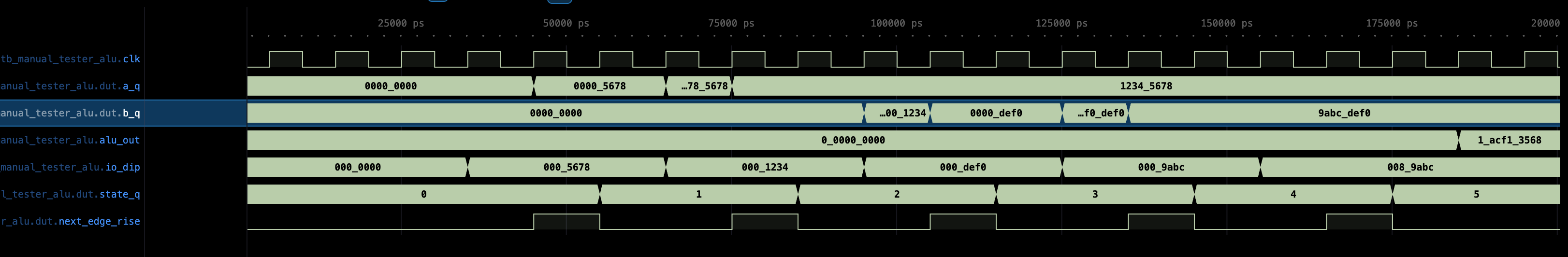
You should see state transition clearly labeled and a, b, alufn value latched, as well as alu output with each io_button[0] press:
Compile and test on Hardware
Once you have both manual and automated ALU tester, you can instantiate both of them in a Lucid project (alchitry_top), and use the dip switches etc to “activate” manual or automated mode.
Summary
Congratulations 🎉🎉! You have successfully built a 32-bit ALU in this lab and familiarse yourself with programming FPGA with Lucid. You will be required to utilise it in Lab 6 (Beta CPU), so please keep a copy of your answer.
Checkoff
Consult the 1D project handout for checkoff procedure. This lab is basically your 1D Checkoff 1.