 50.002 CS
- Overview
- Memory Paging
- Virtual Memory
- Demand Paging
- Context Switching
- Using Cache with Virtual Memory
- Summary
- Next Steps
- Appendix
50.002 Computation Structures
Information Systems Technology and Design
Singapore University of Technology and Design
Virtual Memory
You can find the lecture video here. You can also click on each header to bring you to the section of the video covering the subtopic.
Detailed Learning Objectives
- Explain the Concept of Physical Memory in Computing Systems
- Explain the differences between a program and a process in terms of memory usage.
- Describe how executable instructions and stack allocations influence process memory structure.
- Examine the Role and Functionality of Virtual Memory
- Define virtual memory and discuss its significance in modern computing.
- Justify how virtual memory enables the illusion of a large memory space on systems with limited physical memory.
- Explain Memory Paging and Page Management
- Explain the concept of paging as a method to manage memory efficiently.
- Describe the structure of a page and how it facilitates efficient data transfer between memory and storage.
- Investigate the Process of Address Translation Using the MMU
- Explain the role of the Memory Management Unit (MMU) in translating virtual addresses to physical addresses.
- Identify the components of the MMU and their functions in the context of address translation.
- Outline the Mechanisms of Demand Paging
- Define demand paging and discuss its role in memory management.
- Analyze the process of handling page faults and the criteria for replacing pages in memory.
- Explain Context Switching in Operating Systems
- Discuss the concept of context switching and its importance in multitasking environments.
- Explain how the operating system manages multiple processes through context switching.
- Analyse the benefits and drawbacks of context switching
These learning objectives aim to equip us with a comprehensive understanding of how virtual memory and related concepts function within computer systems, emphasizing their role in managing limited physical resources effectively.
Overview
In our computers, numerous applications operate simultaneously—such as Chrome, WhatsApp, and text editors. Frequently, the number of active processes surpasses the available CPU cores. Each application is designed without knowledge of the other processes it will share resources with. For example, Chrome is programmed to perform its functions without considering the need to share RAM or CPU resources with other programs during its operation.
Program vs Process
A program and a process are terms that are very closely related. Formally, we refer to a program as a group of instructions made to carry out a specified task whereas a process simply means a program that is currently running or a program in execution. We can open and run the same program
Ntimes simultaneously, formingNdistinct processes (e.g: opening multiple instances of text editors). In this course, we relax this strict distinction and use them interchangeably to explain certain concepts easily.
To transform a program into a process, the Operating System (OS) allocates a specific area in the physical memory. This memory image of a single process generally includes the following segments:
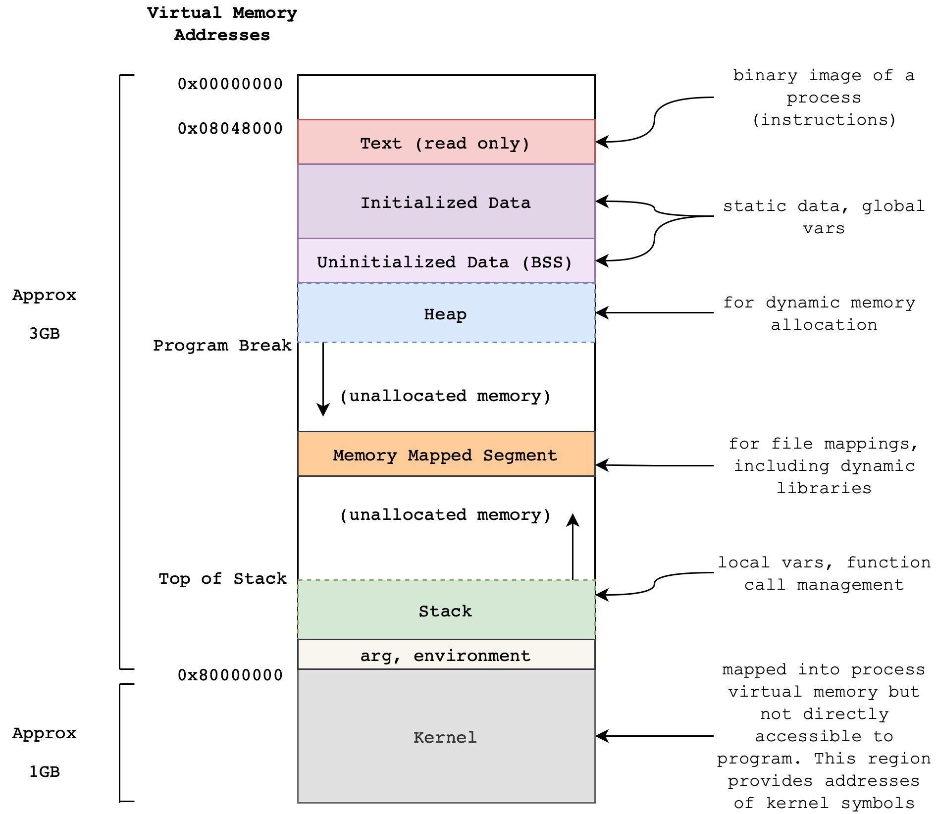
You have already known several segments:
- Read-only segment: contains the process’ executable instruction and data.
- User Stack: this segment can grow during runtime mainly due to function calls (especially recursive ones). For instance, arguments stored at
BP-Naddresses, caller’s old register values, and local variables usually placed at fixed addresses ofBP+M.
Refer to Appendix if you’d like to know more about the other segments.
The point of this illustration is to show that the physical memory alone (in the size of 8-32GB these days in personal computers) definitely is not enough to hold all data required to open many processes at once.
For instance, a size of the PC game Assassin’s Creed Valhalla is at least 77 GB. How is it possible that you can run this game while running the web browser and whatsapp at the same time if your physical memory is only 32 GB in size?
The Swap Space
Swap Space
Swap space is a designated area on a hard drive or other storage device that the operating system uses as virtual memory when the physical RAM is fully occupied. It extends the system’s memory capacity by temporarily storing inactive pages of memory on the disk. When RAM runs low and additional memory is needed, the operating system moves data that hasn’t been used recently from the RAM to the swap space, making room for new data to be processed in the RAM. This process helps prevent the system from running out of memory and slowing down, though accessing data from swap space is generally slower than accessing data from RAM.
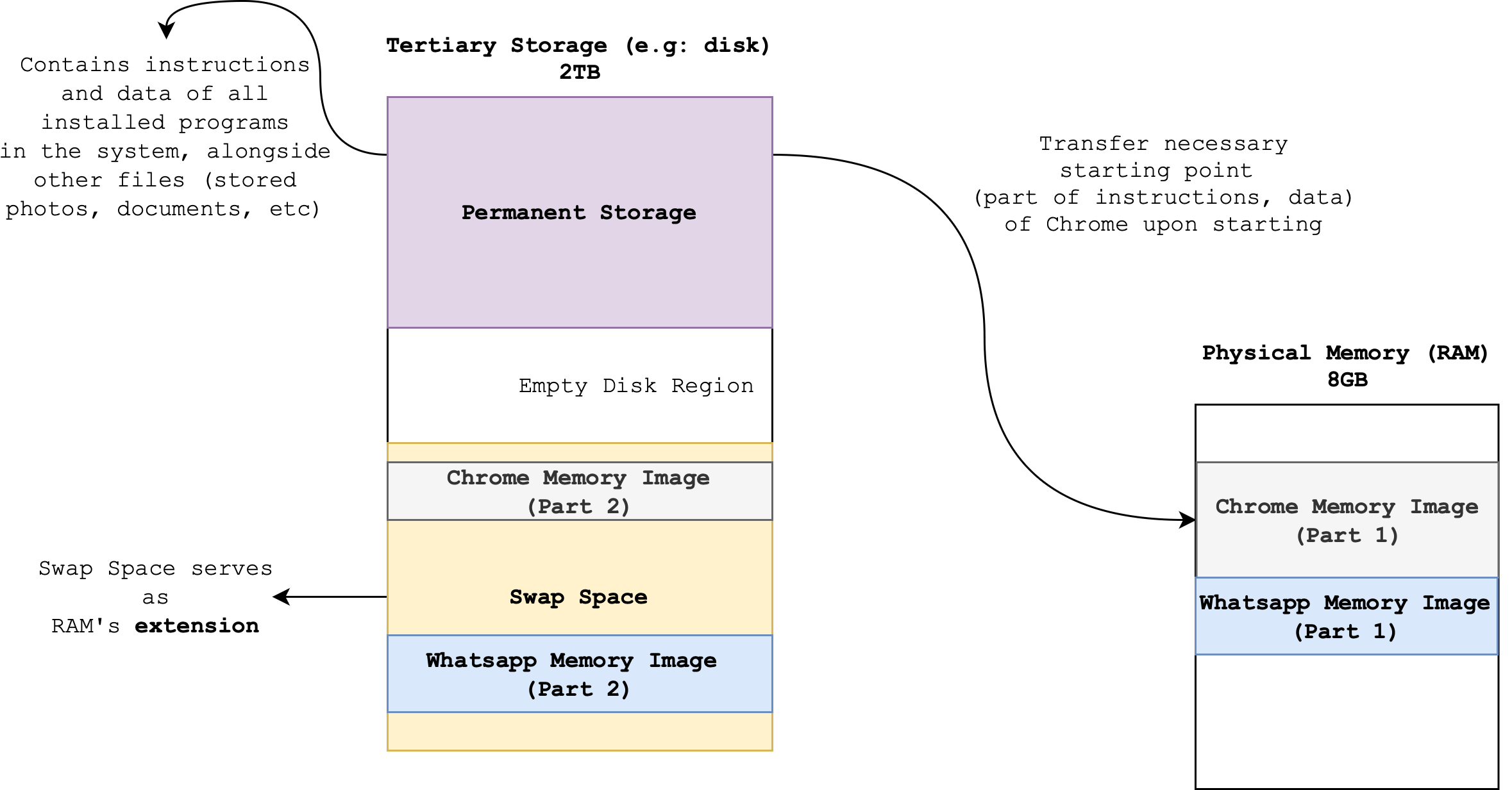
As previously discussed, we often operate multiple processes simultaneously: several web browsers with countless tabs, music players, video editors, photo editors, IDEs, video games, and more. Each of these processes must be loaded from the disk into physical memory before the CPU can access and execute them. The total space needed to accommodate all the information required to run these processes concurrently typically exceeds 4-32GB.
Hence, we need to borrow some free space on the Disk (that are not used to store data) to store the state of currently-run programs. This section is called the disk swap space and it serves as an extension to our physical memory. There are some processes that are *idling and not currently in-use. These are the ones that are stored in the swap space. They will be loaded over to the physical memory again when users resume their usage on these programs.
Operating System Kernel
The part of the computer system that’s responsible for process management is the Operating System Kernel. We will learn more about it next term. The Operating System manages the Swap Space. It has to prioritize. When
Nprograms are opened at the same time, we do not necessarily use them all at once.
Memory Paging
Memory Paging is important concept to highlight before we dive into how virtual memory works.
Paging
Paging is a memory management scheme that is used to store and load data from the disk (large capacity secondary storage) for use in the physical memory efficiently.
For ease of explanation in this notes, you can assume that the word “disk” and “secondary storage” is synonymous.
A Page
A page is a fixed-size block of data that forms contiguous physical memory addresses:

It is very useful and efficient to transfer data in bulk as pages (instead of word by word) between the physical memory and disk due to the locality of reference.
A particular word in a page is addressable by two things:
- A Physical Page Number (
PPN)- This identifies the entire page
- A Page Offset (
PO)- This identifies the word line in a page
PPN + PO makes up the full address of a word in memory.
The number of bits required for page offset PO depends on how many 32-bit words are there in a page (page size).
Example:
- Suppose we have 9 words of data for each page like the page size in the figure above.
- The minimum bits required for
POis:- \(\max(log_2(9)) = 4\) bits if word addressing is used.
- \(\max(log_2(9)) + 2= 6\) bits if byte addressing is used.
PPN Bits
The number of bits in the Physical Page Number (PPN) within a page table entry corresponds to the number of pages that can fit in the physical memory.
For instance, suppose we have physical memory of 20GB in size, and that the size of 1 page is 1GB. There are only 20 pages in total that can fit in the physical memory, hence minimum bits required for PPN is \(\max(log_2(20)) = 5\) bits.
Common Misunderstanding
It is easy to confuse between page size and block size and think that they are related. The truth is that: page size has nothing to do with block size that we learned in the previous chapter (cache).
Virtual Memory
Definition
Virtual Memory is a memory management technique that provides an abstraction of the storage resources so that:
- It is easier for
Nprocesses to share the same limited physical storage without interfering with one another.- It allows for the illusion (to users) of a very large physical memory space without being limited by how much space that are actually available on the physical memory device.
In virtual memory, we use a part of the disk as an extension to the physical memory, and let processes work in the virtual address space instead of the physical (actual) address space. This makes it possible for many processes to seemingly be loaded onto the physical memory at address PC=0 all at once, and having the illusion that it’s run simultaneously, even when their total size exceeds the physical memory capacity.
Programs are loaded to physical memory only when we open (run) them, so that the CPU has direct access to its instructions for execution later on. The majority of your installed programs that are not opened and not run stays on disk.
A computer can run many processes at a time, and therefore all of them have to share the same physical memory. For ease of execution and security, the burden of process management is passed to a very special program: the OS Kernel (details in the next chapter).
The implementation of Virtual Memory is a collaborative effort between both the operating system (OS) and the hardware. The OS is primarily responsible for managing virtual memory (defines the policies for memory management), while the hardware, particularly the CPU and the Memory Management Unit (MMU), is responsible for efficiently executing virtual memory operations
Process Isolation
Each process does not know the existence of another process and everything else that lives in the physical memory. They don’t have to keep track of which addresses in the physical is occupied or free to use, and one process wont be able to corrupt another.
Virtualising the Memory
This provides a layer of abstraction, as the OS Kernel is the only program that needs to be carefully designed to perform good memory management. The rest of the processes in the computer can proceed as if they’re the only process running in the computer.
This way we can say that each process has their own memory, and that is the virtual memory.
Virtual Address
When we launch a new process, the OS Kernel allocates a dedicated virtual address space for all of its instructions (and data required for execution); spanning from low address 0 up to some fixed high address. The addresses requested by the PC are actually virtual addresses (VA) instead of physical addresses (PA). The same applies for LD/ST. The CPU frequently makes memory references through instruction fetch from PC, or LD and ST related instructions.
Physical Address and MMU
Physical address (PA) are actual addresses of each (32 bit) word in the physical memory. Each VA has to be mapped to a PA, so that upon instruction fetch, or LD, the Memory may return the requested data to the CPU. Similarly, upon ST related instructions the CPU should also be able to store the data into the correct PA. This mapping between VA to PA is done via the memory management unit (MMU).

The MMU
An MMU is a hardware unit that sits on the CPU board, along with the CPU itself and the cache. It consists of a context register, a segment map and a page map. Virtual addresses from the CPU are translated into intermediate addresses by the segment map, which in turn are translated into physical addresses by the page map. Its primary function is to process all memory references request from the CPU (
ST/LD) and translateVAintoPA.
How Virtual Addressing Works
Systems that support Virtual Addressing allow for each process to have the same set of VA, e.g: its PC can always start from 0, but in reality they are physically separated from one another.
The figure below illustrates this scenario:

In the example above, there are two currently running processes: process 1 and process 2, each running in its own VM. The actual contents of the virtual memory can either be in the physical memory or at the disk swap space. The processes themselves are not aware that their actual memory space are not contiguous and spans over two or more different hardware. The virtual addresses however, are contiguous.
It is worth reminding that only contents that reside on the physical memory (resident) has a physical address (PA).
Contents that are stored on the disk swap space does not have a PA. If they are needed for access by the CPU, the OS Kernel needs to migrate them over to the Physical Memory/RAM first, so that they have a corresponding VA to PA translation and are accessible by the CPU.
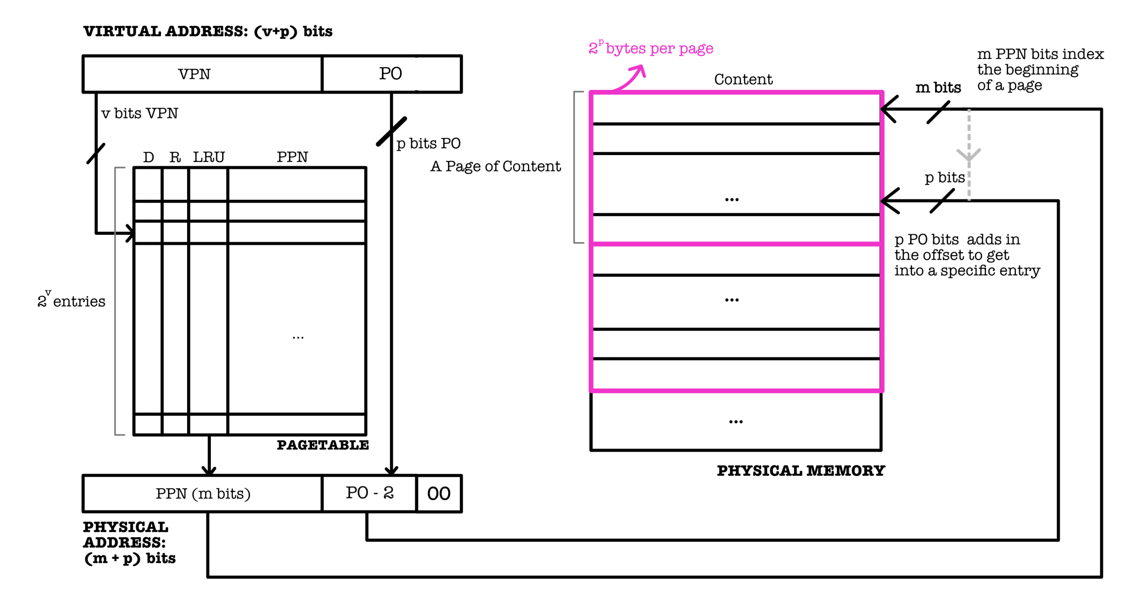
Page Table
The OS Kernel maintains a Page Table (sometimes it is called pagemap too in UNIX environment) that keeps track of the translation between each VA of each process to its corresponding PA. This data structure stores mapping of the higher \(v\) bits of virtual address (called the VPN - Virtual Page Number) to a corresponding PPN (physical page number).
Page Table
The Page table is a data structure used by the operating system to store mappings between virtual addresses and physical addresses. Each entry in the page table contains information about where a specific block of virtual memory is stored on the physical memory. The CPU uses the page table to translate virtual addresses to physical addresses during program execution.
It contains all possible combination of virtual address of a process, but not all
VAhas correspondingPAat a time in the RAM (it may be in the disk).
Number of entries in a Page table
The number of entries in the page table is \(2^v\), because exactly one entry is needed for every possible virtual page.
Page Offset
The PO field of VA is the same as the PO field of its PA. If you always have 00 at the back of PO it simply means BYTE ADDRESSING is used, but the number of bits of PO includes the last two bits. The figure above is just for illustration purposes only.
Page table utilisation
The MMU is a piece of hardware located on the CPU board that helps to perform these operations upon CPU memory reference requests:
- Extract
VPNout ofVA, - Find the corresponding entry in the page table
- Extract the
PPN(if any) - Perform necessary tasks (page-fault handling) if the entry is not resident
- If
PPNfound, append PO withPPNto form a completePA - Pass
PAto other relevant units so CPU request can be completed
In short, the MMU utilizes the page table to translate every memory reference requests from the CPU to an actual, physical address as illustrated below:
Helper Bits
There are three other columns, D (dirty), R (resident), and LRU (if LRU is the chosen replacement policy) in the page table that contains helper bits, analogous to the ones we learned in cache before.
The Resident Bit
The Resident Bit R signifies two cases:
- if
R==1, then the requested content is in the physical memory –PPNin the page table can be returned immediately for further processing to result in a completePA. - if
R==0, then the requested content is not in the physical memory, but in the swap space of the disk. page-fault exception occur and it has to be handled.
“Content” here refers to Mem[PA], that is the content of the Physical Memory at address PA.
The Dirty Bit
Dirty Page
A page is marked as “dirty” if it has been modified (written to) after being loaded into RAM from the disk. This means the page in memory is different from its counterpart on the disk (either in the swap space or the original file location).
If the D==1, then the content of the memory with address PA cannot simply be overwritten. Mem[PA] has to be stored on disk swap space or storage location on disk before it’s overwritten by new data.
The LRU Bit
This bit is present only if replacement policy used is LRU. Just like in cache, it indicates the LRU ordering of the pages resident in the physical memory.
This information is used to decide which page in the physical memory can be replaced in the event that the RAM is full and the CPU asks for a VA which actual content is not resident.
The number of LRU bits needed per entry in the page table is \(v\) (#VPN) bits, since the number of entries in the page table is \(2^v\). We assume a vanilla, naive LRU implementation here, although in practice various optimisation may be done. The LRU bits simply behaves as a pointer to the row containing the LRU PPN, therefore we need at least \(v\) bits and not #\(PPN\) bits.
Page table Arithmetic
This section is difficult and requires patience and practice to excel. Take it easy.
Suppose our system conforms to byte addressing convention. Given a VA of (v+p) bits and a PA of (m+p) bits, we can deduce the following information (assume byte addressing):
- The size of VM is: \(2^{v+p}\) bytes (or \(2^{VA}\) bytes)
- There are \(2^{p}\) bytes per page since we have \(p\) bits of
PO - The actual size of the physical memory is: \(2^{m+p}\) bytes (or \(2^{PA}\) bytes)
- The page table must store \((2 + m) \times 2^v\) bits plus however many helper bits depending on the replacement policy, because:
- There are \(2^v\) rows,
- Each row stores
mbits ofPPN - Each row also has a few helper bits:
2bits forDandR, andmbits forLRUordering (if LRU is used) - Note that actual implementation might vary, e.g: LRU might be implemented in a separate unit
- The \(v\) VPN bits are not exactly stored as entries in the page table, but used as indexing (addressing, eg: using a decoder to select exactly one page table row using \(v\) bits as the selector to the decoder)
The \(v\) bits is often drawn as the first column of the page table. This is just to make illustration easier, but they’re actually used for indexing only as explained in the paragraph above.
Page table Location
The page table is stored in the Physical Memory for practical reasons because of its rather large size. It is expensive to store it in SRAM-based memory device.
Given a VA of size (v+p) bits, the page table must store \((2 + m) \times 2^v\) bits at least, plus whatever helper bits required, depends on the policy.
The OS Kernel manages this page table portion in the physical memory. The MMU device has (or refers to) a component called the Page table Pointer, and it can be set to point to the first entry of the page table in the physical memory (see the figure in the next section for illustration).
Page table pointer
The page table pointer is typically a register or a dedicated location in memory that holds the address of the page table, which is a data structure used to translate virtual addresses to physical addresses in a virtual memory system. It serves as a reference point for the memory management unit (MMU) when accessing the page table to retrieve the physical address corresponding to a given virtual address during memory operations.
Issue
If the page table is solely stored in the physical memory, it forces the CPU to access the (slow) physical memory twice:
- Look up page table to translate the
VAto PA - Access the Physical Memory again to get the content
Mem[PA].
The idea to utilise a portion of the Physical Memory to store the page table comes at the cost of reduced performance. If we were implement the entire page table using SRAM, it is going to be too expensive (in terms of monetary cost).
Solution
The solution to this issue to build a small SRAM-based memory device to cache a few of the most recently used entries of the page table. This cache device is called the Translation Lookaside Buffer (TLB).
TLB: Translation Lookaside Buffer
The TLB is a small, FA-based design cache to store a copy some recently used page table entries, as shown in the figure below:

Caching the page table
We also use a hierarchy of memory devices here, just like what we learned in the previous chapter where we cache a few of the most recently used contents and its address:
A, Mem[A]in another faster (but smaller) SRAM-based memory device to reduce the frequency of access to the slower (but larger) DRAM-based Physical Memory device.
Super Locality of Reference with TLB
We know that there exist a locality of reference in memory address reference patterns, which is why the concept of memory hierarchy (using cache, RAM, and portion of the disk as swap space) is effective. Due to this, there exist a super locality of page number reference patterns (hit-rate of the TLB \(99\%\) in practice).
Also, note that the LRU bits in the TLB is not the same as the LRU bits in the page table. The reason is that the number of N entries in the TLB is always the N most recently accessed pages out of \(2^{v}\) possible entries in the page table, where N < \(2^v\) in practice.
Demand Paging
Definition
Demand paging is a method of virtual memory management.
The OS Kernel is responsible for the implementation of demand paging, and it may vary from system to system. However, the main idea of demand paging is that data is not copied from the swap space to the physical memory until they are needed by the CPU.
For now, let’s ignore the presence of data cache and TLB for the sake of simplicity in explanation. We will add it back to the picture later on.
When a computer is turned off, every bits of information is stored in its non-volatile memory storage (disk, NAND flash, etc). The physical memory is incapable of storing any information when it does not receive any power source. The OS Kernel is one of the first programs that is loaded onto the physical memory when our computer is started up. It maintains an organised array of pages on disk.
Do not trouble yourself at this point at figuring out how bootstrap works, i.e: how to load the OS Kernel from the secondary storage to the physical memory. We will learn more about this next term.
The moment a request to execute a program is made, the OS Kernel allocates and prepares the virtual memory space for this program on the RAM:
- This space is defined by the process’s addressable memory range (range of addresses that the process can use for its execution), which can include both code (instructions) and data.
- The size and layout of this space are defined by the OS and are based on the process’s needs and the system’s architecture (e.g., 32-bit vs. 64-bit systems have different address space sizes).
- Only a small subset, essentially the program’s entry points (elf table, main function, initial stack) is put onto the physical memory, and everything else is loaded later. The actual loading of these into physical memory, however, is managed by demand paging, meaning that they are loaded as needed.
- Other details such as page table initialization, mapping of executable libraries, etc. We shall not dwell into this because implementation varies from OS to OS.
The OS also prepares for scenarios where physical RAM might be insufficient by setting up swap space (on disk) where inactive pages can be stored temporarily, allowing more active processes to utilize the physical RAM
When the process attempts to access memory that hasn’t yet been loaded (ever, first-time) into physical RAM (causing a page fault), the OS loads the required data from storage (not swap space) into RAM, updates the page table to reflect the physical location, and then resumes process execution.
- As the process runs longer, more and more of its content (data/other instructions) are stored on RAM.
- When the RAM is full the OS Kernel swap some pages out of the RAM (inactive pages) onto the disk swap space. If the process requires this page back, this again will trigger a page fault and the OS loads the required data from the swap space into RAM, updates the page table, and resumes process execution.
Summary
Let’s summarise how demand paging works in a nutshell:
- At first (when the process has just been opened), majority of its content is still on the disk and only its entry point is loaded to the RAM to be executed by the CPU.
- Subsequent pages belonging to that process will only be brought up to physical memory (either from storage region of disk for first-time usage or swap-space for bringing back inactive pages) if the process instruction asks for it.
This setup is fundamental to modern operating systems, allowing them to efficiently manage memory, provide security and isolation among processes, and enable complex multitasking and applications that require memory beyond the physical limits of the system.
Page-Fault Exception
Upon execution of the first few lines of instruction of the process’s entry point, the CPU will request to refer to some VA, and it will result in page-fault exception because almost all of its virtual addresses are not resident in the physical memory yet at this point.
The OS Kernel will then handle this “missing” page and start copying them over to the physical memory from the swap space (or other parts of disk if it’s first-time access ever), hence turning these pages to be resident, which means that it has a PPN assigned to it. The kernel then updates the corresponding entry of the page table and the TLB.
Many page faults will occur as the process begins its execution until most of the working set of pages are in physical memory (not the entire process, as some processes can be way larger than the actual size of your physical memory, e.g: your video games). If you’re interested to know how VA is mapped to swap space, refer to this section in Appendix.
In other words, the OS Kernel bring only necessary pages that are going to be executed onto the physical memory as the process runs, and thus the name demand paging for this technique.
Replacing Resident Pages
This process (of fetching new pages from swap space to the physical memory) eventually fills up the physical memory to the point that we need to replace stale ones.
If a non-resident VA is enquired and the physical memory is full, the OS Kernel needs to remove some pages (LRU/FIFO, depends on the replacement policy) that are currently resident to make space for this newly requested page.
If these to-be-removed pages are dirty (its copy in the disk swap space is not the same as that in the RAM), a write onto the disk swap space (or permanent storage space, depending on usage case) is required before they’re being overwritten.
- The kernel maintains a data structure that keeps track of the status of each resident page in the physical memory.
- This data structure is often referred to as the “page frame database” or “page table”. It contains information such as the VPN, PPN, and the access status (clean or dirty) of each page.
When a page is marked as dirty, it indicates that its contents have been modified in the RAM and differ from the contents in the swap space or permanent storage space. In such cases, before the dirty page can be replaced, the kernel writes the updated contents back to the swap space to ensure data consistency. Once the dirty page has been written back to the swap space, the kernel can then safely replace it with the newly requested page in the physical memory.
Conclusion
This process of replacing resident pages helps maintain an efficient utilization of the available memory and ensures that only the most relevant and frequently accessed pages are kept in the physical memory, while the less frequently accessed pages are stored in the swap space.
Process Termination
Finally when the process terminates, the OS Kernel frees up all the space initially allocated for this process’s VM (both on physical memory and disk swap space).
Exercise
This section puts the knowledge about demand paging and virtual memory to practice.
The figure below shows a snapshot of the physical memory state at some point in time. There exist a page table with 16 entries and 8 pages of data labeled as A to H in the physical memory. LRU replacement policy with write back policy is used. Lower LRU means that the data is more recently used. Each page contains exactly 256 bytes of data.

The above information gives us five clues:
VPNis4bits longPPNis at least3bits longPOis8bits longVAis8+4 = 12bits longPAis3+8 = 11bits long
We can assume that instructions are located at a separated physical memory (like our Beta), so we can spare ourselves the headache of resolving virtual to physical memory addresses on both instruction loading and data loading (LD and ST operations).
Assumption
We assume for the sake of this exercise only that we are looking at the portion of the RAM, page table, and TLB that stores data only and NOT instruction. Please read the questions carefully in quizzes or exams/tests.
Example 1
Now suppose the current instruction pointed by the PC is LD(R31, 0x2C8, R0). This means a memory reference to address 0x2C8 is required.
We know that 0x2C8 is a virtual address (because now our CPU operates in the VA space), and hence we need to obtain its physical address. Segmenting the VA into VPN and PO:
VPN: 0x2(higher 4 bits)PO: 0xC8(lower 8 bits)
Looking at the page table, we see that VPN: 0x2 is resident, and can be translated into PPN: 100. The translated physical address is therefore 100 1100 1000. In hex, this is 0x4C8. The content that we are looking for exists within page E.
Example 2
Suppose the next instruction is ST(R31, 0x600, R31). This means a memory reference to address 0x600 is required.
We can segment the VA into:
VPN: 0x6(higher 4 bits)PO: 0x00(lower 8 bits)
From the page table, we see that VPN: 0x6 is not resident. Even though PPN: 5 is written at the row VPN: 6, we can ignore this value as the resident bit is 0.
This memory reference request will result in page fault.
- The OS Kernel will handle this exception, and
- Bring the requested page (lets label it as page
I) into the RAM.
Now suppose the RAM is currently full. We need to figure out which page can be replaced.
- Since LRU policy is used, we need to find the least recently used page with the biggest
LRUindex - This points to the last entry where
PPN:3(containing pageD) andLRU:7.
However, we cannot immediately overwrite page D since its dirty bit is activated. A write (from the physical memory to the swap space of page D) must be performed first before page D is replaced with the new page I.
After page D write to its corresponding location in swap space is done, the OS Kernel can copy page I over from the swap space to the physical memory, and update the page table:
VPN:Fdirty bit is cleared, and resident bit is set to0.VPN:6is updated, as now it is mapped toPPN:3. Its resident bit is set to1.- After write (
ST), its dirty bit is also set to1. - All entries’ LRU bits must be updated accordingly.
The state of the physical memory after both instructions are executed in sequence is as shown. The new changes are illustrated in blue:
I' is just a symbol of an updated page I after a ST instruction is completed

Think!
Enhance your understanding by adding TLB into the picture. If a TLB contains VPN 2 -> 4, and VPN 7 -> 2 entries in the beginning, what would its content be after the two LD and ST access?
Context Switching
Context Switching
Context switching is the process where an operating system saves the current state of a running process (or thread) and then loads the state of another process, allowing the CPU to switch between different tasks.
It is a strict procedure that a CPU must follow when changing the execution of one process with another. This is done to ensure that the process can be restored and its execution can be resumed again at a later point. A proper hardware support that enables rapid context switching is crucial as it enables users to multitask when using the machine. We learn about this in more depth next term.
A single core CPU is capable of giving the illusion that it is running many processes at the same time.
What actually happens is that the CPU switches the execution of each process from time to time. It is done so rapidly that it seems like all processes are all running at once as if we have more than one CPU. This technique is called rapid context switching.
This is analogous to how animated videos tricks the eye: each frame is played only for a fraction of a second such that the entire video appears “continuous” to us.
Processes in Isolation
Each process that are running in our computers have the following properties:
- Each has its own virtual memory (it’s like giving the illusion that each process has independent physical memory unit all for itself)
- Therefore every process can be written as if it has access to all memory, without considering where other processes reside.
For example, the VA of each process can start from 0x00000000 onwards but it actually points to different physical addresses on disk.
Context Number
To distinguish between one process’s VA address space with another, the OS Kernel assigns a unique identifier C called context number for each program.
The word context refers to a set of mapping of VA to PA.
The context number can be appended to the requested VPN to find its correct PPN mapping:
- A register can be used (added as part of the MMU hardware or the CPU) to hold the current context number
C. - The TLB
TAGfield contains bothCandVPN. - In the case of
MISS, the page table Pointer is updated to point to the beginning of the page table section for contextC, and the index based onVPNfinds the corresponding entry.

With context numbering, we do not have to flush (reset) the TLB whenever the CPU changes context, that is when switching the execution of one process with another. It only needs to update the page table pointer so that it points to the start of the page table section for this new context.
If you’re interested to know more about how the page table pointer is updated in practice using the context number, refer to this section in Appendix.
Using Cache with Virtual Memory
We know that a cache is used to store copies of memory addresses and its content: A, Mem[A], so that CPU access to the physical memory can be reduced on average. There are two possible options on where to assemble the cache hardware, before or after the MMU, each having its pros and cons.

If a cache is placed before the MMU, then the cache stores VA (instead of PA) in its TAG field. Otherwise, it will store PA instead of VA.
However, both VA and PA share the same Page Offset PO. If a cache line selection is based on PO, then two computations can happen in parallel:
VPNtoPPNtranslation and,- Finding the correct cache line in DM / NWSA cache
We can leverage on this fact by creating a hybrid arrangement:
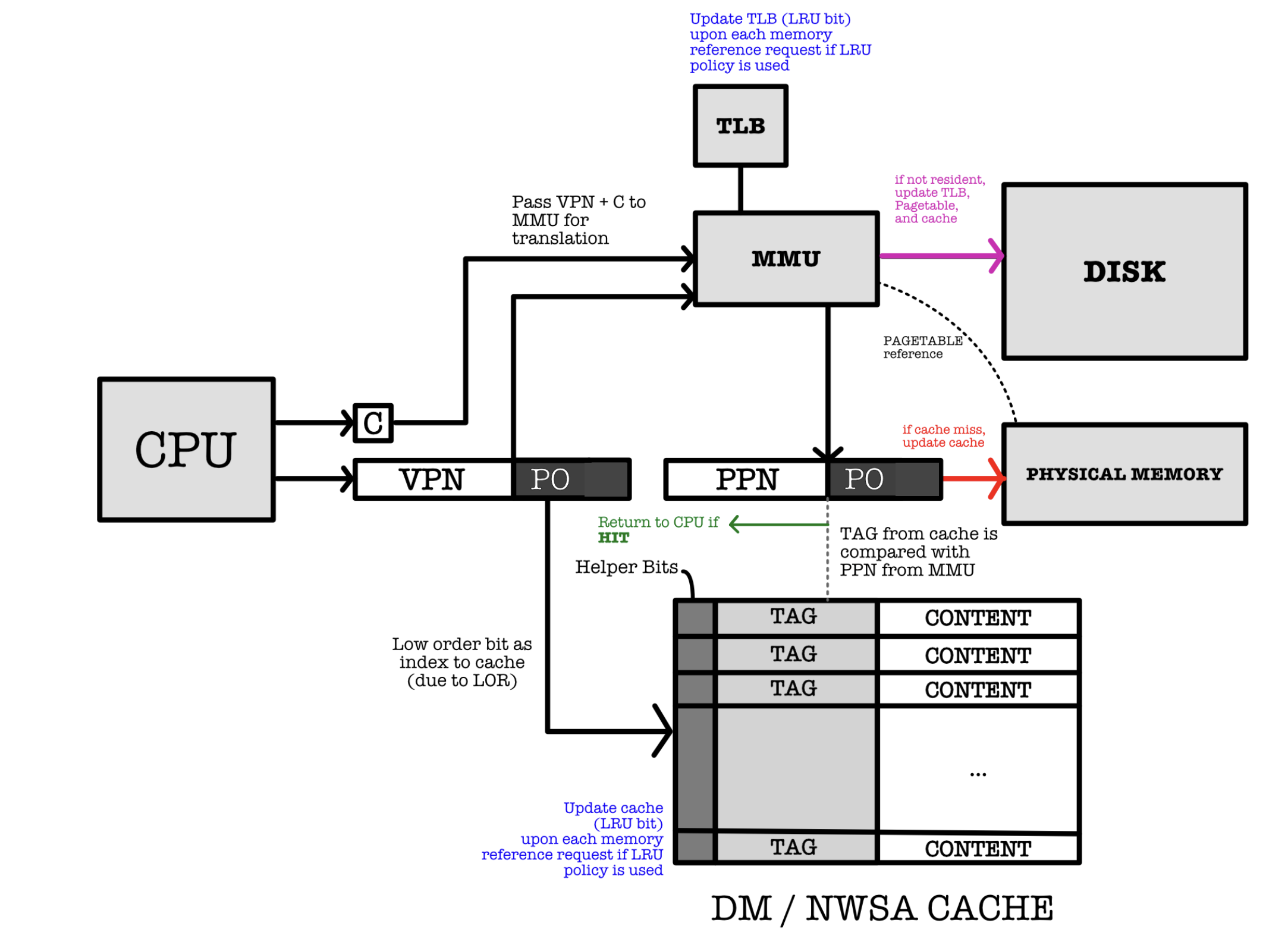
Each cache line in the DW/NWSA used in the design above stores:
- The data word ((not pages)) in its
Contentfield and - The physical address in the
TAGfield.
The index of the tag in the cache is set to be the PO of the VA due to locality of reference. If higher order bit is used to index the cache lines then we will end up with cache contention.
Think!
Why is it not practical if we use the higher order bits to index the cache line?
Further Analysis
What happens if the a requested page is Resident but results a cache MISS?
The cache **must** be updated by fetching the new data from the Physical Memory.
What happens a requested page is Not Resident?
Page must be fetched from the swap space and copied over to the Physical Memory. This triggers an update to the page table and TLB. Afterwards, we have update the cache.
Practice
Ask yourself these questions to further enhance your understanding:
- What happens if the page is
Not Residentand if Physical Memory is full? Assume LRU policy is used.- Which part of the TLB that we need to update on each memory reference request? What about the cache? Why?
- What should be done if TLB
MISShappens?- Is it possible for cache
HITto occur but the requested page is not resident? Why or why not?
Summary
You may want to watch the post lecture videos here.
Virtual Memory is a memory management technique that provides an abstraction of the storage resources so that programs can be written as if they have full access to the physical memory without having to consider where other processes reside. It allows computers to handle large and multiple applications beyond the physical memory limits by using disk space as an extension of RAM. It employs a memory management scheme called paging, where the Memory Management Unit (MMU) plays a critical role in translating virtual addresses to physical locations using page tables. Techniques such as demand paging and the use of Translation Lookaside Buffers (TLB) optimize this process, making efficient use of system resources and improving application performance.
The Virtual Memory is crucial for handling multiple processes in modern computing environment.
Here are the key learning points:
- Virtual Memory: An extension of physical memory that allows for larger program execution than the available physical memory and supports safe memory sharing among multiple processes. It is a technique that simulates more memory space than is physically available, using disk space for excess data.
- Basic implementation: The OS implements the logic and policy for virtual memory, while the hardware provides the mechanism for efficient translation and enforcement.
- Memory Paging: Paging is a method for efficient memory use. Pages of a predetermined size (by the OS) are moved between disk and RAM.
- Address Translation: The CPU (user mode) operates in virtual address space. The Memory Management Unit (MMU) converts virtual addresses to physical addresses.
- Page Table Management: The page table (residing in RAM) is used for maintaining the mapping of virtual to physical addresses.
- Demand Paging and TLB: Demand paging is a memory management technique where pages are loaded into physical memory only when they are accessed, reducing the need to load an entire program into RAM upfront. The TLB is a hardware cache in the CPU that stores recent virtual-to-physical address translations, speeding up memory access by reducing the need to consult the page table repeatedly.
Next Steps
In the next chapter, we will learn how Virtual Memory is used to create Virtual Processor (Virtual Machine). Specifically, to learn how the OS Kernel is specially privileged program (not a process, but you may not be able to understand this statement fully now and that’s okay) is responsible of managing hardware resources in a system and scheduling processes to share these limited resources, thus allowing each process to run independently on its own virtual machine. The OS Kernel is responsible for process scheduling. Each process is running in an isolated manner from one another (in its own virtual space, unaware of the presence of other processes), the OS Kernel can switch execution between programs – giving the users an illusion as if these processes are running simultaneously with just a single CPU. The procedure that allows for this to happen seamlessly is called rapid context switching.
Context switching allows for timesharing among several processes, that is to share the CPU amongst multiple process executions.
The OS Kernel loads the appropriate context number and page table pointer when switching among processes. This way, the CPU can have access to instructions or data required to execute each process and switch executions between processes.
Appendix
Generic Runtime Memory Layout
The image above depicts a generic runtime memory layout of a process in RAM. At the top, starting with the lowest memory address, is the read-only segment which typically contains the code (text segment) of the program, including all the compiled instructions. It’s made read-only to prevent the program from accidentally modifying its instructions.
Below the text segment is the static segment for both initialized and uninitiliazed variables that persist for the lifetime of the program. The initializd segment stores the global variables and static (both local and global) variables that are explicitly initialized by the programmer. For example, if you declare a global variable with an initial value like int total = 100;, it would be stored in the data segment. The values in this segment are directly loaded from the executable file when the program starts.
The term “BSS” stands for Block Started by Symbol, a segment used in the memory layout of a program to store static variables that are not explicitly initialized by the programmer. When a program is executed, the operating system initializes the data in the BSS segment to zero. This segment includes:
- Static variables declared globally but not initialized. For example,
static int count;in C would be part of the BSS. - Static variables within functions that are not initialized. For example,
static int last_value;in a function would also reside in the BSS.
The purpose of the BSS segment is to efficiently manage the uninitialized static data. Since all variables in BSS are initialized to zero, the operating system doesn’t need to store the initial values; it only needs to allocate space for them. This reduces the size of the program on disk because only the space allocation, not the initial content, needs to be recorded.
Both of the initialized and uninitialized data segments are part of the static memory allocation of a program, meaning their size is fixed at compile time and doesn’t change during program execution. This allocation strategy helps in efficiently managing memory for global and static variables throughout the life of the program.
Stack
Next comes the stack, which grows downward (towards increasing memory address) as shown. The stack is used for local variables and is dynamically allocated and deallocated as functions are entered and exited, respectively. Local variables are stored here along with information necessary for function calls, such as return addresses and parameters.
Stack Overflow
Since the stack has a limited size, excessive use of the stack (for example, through deep recursion or allocating large local variables) can lead to stack overflow. This is a common issue in programming where the stack exceeds its allocated space, potentially leading to program crashes or security vulnerabilities.
Memory Mapped Segment
Below the stack is the memory-mapped (MMAP) region, which is used for shared libraries and for memory-mapped files. It can vary in size and location within this region depending on the operating system and the libraries in use. This region typically exists between the heap and the kernel space in a process’s virtual memory layout. The mmap region is used for:
-
Memory-Mapped Files: Allowing files or devices to be mapped in memory for efficient file I/O operations. This means that a file can be treated as a part of the application’s memory, allowing both reading from and writing to the file through memory operations.
-
Dynamic Libraries: Loading shared libraries into a process’s address space. Instead of including a copy of the library’s data in every process that uses it, the system maps the library into the virtual address space of the process.
-
Anonymous Mappings: Creating memory areas that are not backed by any file, commonly used for dynamically sized data structures or inter-process communication buffers.
In the provided diagram, we draw the mmap region would to be located above the heap. The heap grows upwards (towards higher addresses), and the mmap area would be above it before the kernel space starts. It’s often left out in simplified diagrams because it’s size and location can vary significantly between different processes and depending on how the process is using memory-mapped files or shared libraries. Additionally, it’s not a fixed-size region and can grow or shrink as needed, unlike the stack or the data/BSS segments which have more predictable sizes once the program has started.
Heap
The runtime heap follows the MMAP region and grows upwards; this is where dynamic memory allocation occurs (e.g., when using malloc in C or new in C++). Memory is allocated and freed on demand here. We don’t go into too much details on how to maintain heap during runtime in this course. For those who are interested, you can read these external materials.
The heap is a crucial area in memory used for dynamic memory allocation. Unlike the stack or static (global and BSS) segments where the size and lifetime of memory allocation are determined at compile time, the heap allows for the allocation of memory at runtime. Here’s what typically gets stored in the heap:
- Dynamically Allocated Memory: Whenever a program requires memory during its execution and the size of this memory isn’t known beforehand, the memory is allocated on the heap. This includes scenarios such as:
- Memory for objects when new instances are created in object-oriented programming.
- Memory allocated for arrays or other data structures whose size depends on runtime conditions.
-
User-Controlled Lifespan: Unlike stack memory, which is automatically managed and has a very structured push/pop behavior tied to function calls and returns, heap memory must be explicitly managed by the programmer. In languages like C and C++, this involves using
mallocornewto allocate memory andfreeordeleteto release it. In higher-level languages like Python or Java, this memory management is handled by garbage collection. -
Flexibility and Limitations: The heap provides great flexibility because it allows programs to manage available memory more dynamically based on changing needs during execution. However, this flexibility comes with overheads. Heap memory management is generally slower than stack-based memory access, and improper management can lead to issues like memory leaks, where memory is not properly released back to the system.
- Large Objects: Typically, large objects and structures are allocated on the heap because the stack has a much more limited size and could quickly overflow with large allocations.
The heap grows and shrinks dynamically as objects are created and destroyed, making it well-suited for situations where you do not know in advance how much memory you will need.
Kernel
Finally, the kernel memory space resides at a specific region the bottom (higher memory address), directly mapped to the kernel code and kernel modules. It is protected and segregated from user-space processes; the kernel operates in a different mode with higher privileges, and user processes cannot directly access this area. User processes can interact with the kernel through system calls, which switch the CPU to kernel mode to execute privileged operations.
The depicted addresses are illustrative and can differ based on the operating system and the machine’s architecture. For example, the direction of growth for the stack and heap is Operating System dependent. Some stack may also grow upwards (towards decreasing memory address), but the idea remanins the same.
The operating system (OS) does not know in advance whether stack or heap will be used predominantly before the program is actually running. Therefore, an OS must layout these two memory regions in a way to guarantee maximum space for both, and therefore a Stack that grows downwards and Heap that grows upwards are typically placed towards the opposite end of one another.
The Null Space
In a typical memory layout for a process, the region from address 0x00000000 up to around 0x08048000 (or a similar starting point for the text segment) is intentionally left empty, and this is often referred to as the “null space” or “zero page.” This area is reserved and kept unused for several important reasons:
-
Protection Against Null Pointer Dereferences: By keeping this area empty, any dereference of a null pointer (which is conventionally zero or near zero) will lead to a segmentation fault or similar crash. This behavior acts as a safety feature, preventing the program from inadvertently using a null reference to read or write data, which can lead to unpredictable behavior or security vulnerabilities.
-
Debugging Aid: Having a null space makes it easier to catch bugs related to null pointer dereferences during the development and debugging phases, as accessing this area will immediately cause a noticeable crash.
-
Security: The null page is intentionally left unmapped to make exploitation of software bugs harder. Many exploits rely on controlling the pointer values, and if they mistakenly point to a low address, the operating system ensures that it results in an error rather than allowing an attacker to execute arbitrary code.
The text segment typically begins immediately after this null space, at addresses such as 0x08048000, where the executable code of the program is loaded. This is the region where the compiled machine code of the program resides and is executed from. The clear division between the null space and the text segment is part of enforcing memory protection and maintaining an orderly and secure execution environment.
Mapping VA to Swap Space
This section is out of syllabus, and written just to complete your knowledge.
The page table holds more information than just VPN to PPN translation, but also some information about where that VPN is saved in the swap space (if any). This section is also called the swap table (depending on OS). Recall that Page Table Entry is not removed when the corresponding page is swapped out of memory onto the swap space. The page table must always have 2^VPN entries. (each VPN corresponds to an entry). There exist a reference to the swap block (a region containing the swapped out page on disk) for non-resident VPN which page exists only in the swap space. The actual implementation of the “pointer” that can directly access the disk swap space is hardware dependent.
The size of the swap space depends on the OS setting. In Linux OS, the size of the swap space is set to be double of the RAM space by default. You can read this site to learn more about swap space management in Linux.
Sometimes you might have this misunderstanding that Virtual Address is equal to “swap space address”. In reality, the relationship between virtual pages and swap space is managed through a series of mappings and tables (such as page tables, swap tables, and others) that track whether a page is in physical memory, on disk, or not currently allocated. The mapping also handles the translation between virtual addresses and physical addresses or swap space locations. These details are essential for understanding the full complexity of virtual memory systems, but are abstracted in 50.002.
Page Table Pointer
As mentioned above, the page table pointer is a register or a dedicated location in memory that holds the address of the page table.
With context numbers, which are often used in systems that support tagged TLBs (Translation Lookaside Buffers), the page table pointer points to the base of the page tables for the current context or process. The context number helps the MMU distinguish between different address spaces, ensuring that the translations are performed within the correct context, corresponding to the active process or task using the memory at that time.
Physical Location of the Page Table Pointer
This pointer that indicates the base of the page table for the current process is typically stored in a special register within the CPU. This register is updated during a context switch to point to the page table of the process that is being switched to.
The actual name and mechanism of this register can vary depending on the CPU architecture. For example, on x86 architectures, this is the CR3 register, also known as the Page Directory Base Register (PDBR) in x86 terminology. It points to the base of the page directory, which is the top-level structure in the multi-level page table system used by these CPUs. When a context switch occurs, the operating system updates the CR3 register with the physical address of the page directory of the process that is about to run.
Thus, while the MMU is responsible for the address translation process, the CPU holds the register that points to the base of the page table of the current process.
PBTR
The actual start of the page table, also known as the base address of the page table, is typically stored in a special-purpose CPU register. This register is often referred to as the page table base register (PTBR) or sometimes as the page directory base register (PDBR), depending on the architecture and the level of paging used. It is designed to be quickly accessible by the MMU, which is also a part of the CPU, specifically for performing tasks related to virtual-to-physical address translation.
When a context switch occurs (switching from one process to another), the operating system’s kernel updates this register to point to the page table of the new context, thereby allowing the memory management unit (MMU) to translate virtual addresses using the correct page table for the process that is currently scheduled to run.
In architectures that use multiple levels of page tables, such as a multi-level page table or inverted page table, the base register typically points to the top-level table. From there, the MMU can navigate through the hierarchy of tables to find the actual physical address.
When a virtual address needs to be translated to a physical address, the MMU uses the value in the PTBR to find the starting point of the current page table. The MMU, being an integral part of the CPU’s architecture, handles the translation with the data provided by this register. In modern architectures, the CPU and MMU work closely together, sharing several registers and control mechanisms to manage memory efficiently. The PTBR is just one of the many control registers that facilitate this management.
Context Number Location
The context number is usually stored in one of the CPU’s internal registers when it’s actively being used to reference the current context. In systems that use context numbers, the operating system maintains a context table, and the context number acts as an index into this table. The detail differs from architecture to architecture.
In the x86 architecture, there isn’t a specific “context number” used for memory management during context switches; instead, the CR3 register is updated to point to the page directory of the current process, handling context changes at the level of page tables.
For ARM architecture, the context for memory management is managed using the Translation Table Base Registers (TTBR0 and TTBR1) for different parts of the address space, and the Context ID Register, which stores an identifier used to tag TLB entries and ensure process isolation.
In SPARC architecture, the context number is stored in a special register called the Context Register. This register is part of the Memory Management Unit (MMU), and it’s used to keep track of the current context. When a context switch occurs, the operating system updates the Context Register with the context number of the new process.
In summary, the context number is stored within a register of the MMU or CPU that is specifically designed for this purpose. The actual location and name of this register can vary depending on the computer architecture.
CPU Special Registers
Special registers in a CPU are dedicated registers that serve specific control and status functions beyond general data handling. These registers play critical roles in CPU functionality, affecting everything from basic arithmetic to advanced features like virtual memory management and system security.
In \(\beta\) CPU, we do not have special registers apart from the PC register. We even utilise its MSB to signify machine mode (Kernel vs User mode) as we will not be utilising all 32-bits of address space in practice.
Special Registers in ARM Architecture
- Program Counter (PC): Holds the address of the current instruction being executed.
- Link Register (LR): Stores the return address for subroutines.
- Stack Pointers (SP): Separate stack pointers for user and interrupt modes.
- Current Program Status Register (CPSR): Contains condition flags and current processor state information.
- Saved Program Status Registers (SPSRs): Used in exception handling to save the CPSR of the current context.
- Translation Table Base Registers (TTBR0 and TTBR1): Point to the base of the active translation tables for different parts of the memory map.
- Context ID Register: Used for tagging TLB entries with an identifier to maintain process isolation.
Special Registers in x86 Architecture
- Accumulator Register (EAX/AX/AH/AL): Used in arithmetic operations, I/O, interrupts, etc.
- Base Register (EBX/BX/BH/BL): Used as a pointer to data in the DS segment (data segment).
- Count Register (ECX/CX/CH/CL): Used in shift/rotate instructions and loops.
- Data Register (EDX/DX/DH/DL): Used in I/O operations, arithmetic, and more.
- Stack Pointer (ESP/SP): Points to the top of the stack.
- Base Pointer (EBP/BP): Used to point to the base of the stack in the current frame.
- Instruction Pointer (EIP/IP): Holds the address of the next instruction to be executed.
- Segment Registers (CS, DS, ES, FS, GS, SS): Point to segments used for code, data, and stack.
- Flags Register (EFLAGS/FLAGS): Contains status flags, control flags, and system flags that reflect the current state of the CPU.
- Control Registers (CR0, CR1, CR2, CR3, CR4): Control machine functions, such as memory management (e.g., CR3 holds the base address of the page directory).