 50.002 CS
- Mixing Blocking and Nonblocking Assignments in a Single Clocked Block
- Undesirable Order-Dependent Behavior
- Accidental Pipeline Collapse (Ordering Effect Inside the Same Block)
- Things “Work” in a Single Block, Fails When Split Into Multiple Blocks
- Ensure Safety When Using Temporaries in a Clocked Block
- Output Computation Depends on a Register Being Updated in the Same Edge
- Summary
- Issues on Using Nonblocking Assignments in Combinational Logic
- Synthesis Inference vs Simulation Semantics
- Multiple Always Blocks Driving the Same Register is Illegal
- Latch Inference Is Independent of Assignment Operator
- Testbench Races at Clock Edges
- Issues on Using Blocking Assignment in a Clocked
always @(posedge clk)Block
50.002 Computation Structures
Information Systems Technology and Design
Singapore University of Technology and Design
Nuances of Blocking and Nonblocking Assignments in Verilog
This article documents subtle but important semantic consequences of blocking (=) and nonblocking (<=) assignments. While synthesis often infers identical hardware, incorrect assignment usage can lead to misleading or nondeterministic simulation results.
All examples are written in Verilog-2005.
Mixing Blocking and Nonblocking Assignments in a Single Clocked Block
Blocking and nonblocking assignments may coexist in a clocked always block only if their roles are clearly separated.
- Blocking assignments may be used for temporary combinational calculations,
- Nonblocking assignments must be used for state updates.
In short, a single clocked process can contain BOTH (i) computations that are conceptually combinational and (ii) register updates. This is legal Verilog and it often synthesizes into correct hardware. However, the moment the computation depends on values that are also being updated on the same clock edge, the simulation (not hardware!) meaning becomes sensitive to assignment type and statement ordering.
The core distinction is:
- A flip-flop samples inputs at the clock edge and updates outputs simultaneously.
- A clocked
alwaysblock executes sequentially in the simulator, so the code must be written to emulate simultaneous sampling.
When a design is written as “one big posedge always,” it is easy to accidentally encode sequential, software-like behavior, even though the intended hardware is parallel.
This section catalogues concrete “weird cases” that arise.
Undesirable Order-Dependent Behavior
Mixing assignment types for state variables introduces order-dependent behavior, which is highly undesirable because that means you will end up with different outcome depending on the simulator/compiler used.
This is a corect mixing example:
always @(posedge clk) begin
  tmp = a ^ b;   // temporary computation
  q   <= tmp;    // state update
end
| Expected Hardware Intent | Observed Simulation Behavior |
|---|---|
One flip-flop storing q |
Matches hardware intent |
Input to the flip-flop is a ^ b |
No race or ambiguity |
This is a counterexample:
always @(posedge clk) begin
  q1 = d;
  q2 <= q1;
end
Issue
q2may observe the updated value ofq1within the same cycle, collapsing a pipeline stage in simulation.
Accidental Pipeline Collapse (Ordering Effect Inside the Same Block)
Assume we want to make two flip-flops in series. The expected behavior is:
q1(t+1) = d(t)q2(t+1) = q1(t)(one additional cycle delay)
This is a bad attempt to implement it:
module pipe_collapse_blocking(
  input  wire clk,
  input  wire rst,
  input  wire d,
  output reg  q1,
  output reg  q2
);
  always @(posedge clk or posedge rst) begin
    if (rst) begin
      q1 = 1'b0;
      q2 = 1'b0;
    end else begin
      q1 = d;
      q2 = q1;  // reads updated q1 in simulation
    end
  end
endmodule
What you might see:
q2behaves like it samples the newq1immediately.- The design appears to have one fewer cycle of latency in simulation.
You can try it yourself with this testbench:
`timescale 1ns/1ps
module tb_pipe_collapse;

  reg clk, rst, d;
  wire q1, q2;

  pipe_collapse_blocking dut(.clk(clk), .rst(rst), .d(d), .q1(q1), .q2(q2));

  initial begin clk = 0; forever #5 clk = ~clk; end

  initial begin
    $dumpfile("tb_pipe_collapse.vcd");
    $dumpvars(0, tb_pipe_collapse);

    rst = 1; d = 0;
    #12 rst = 0;

    #3 d = 1;
    #10 d = 0;
    #10 d = 1;
    #20 $finish;
  end

endmodule
Things “Work” in a Single Block, Fails When Split Into Multiple Blocks
A monolithic clocked block using blocking assignments can appear correct because the sequential ordering is consistent within that block. The design often fails when refactored into separate always blocks (or separate modules), because the simulator is free to schedule those blocks in either order at the clock edge.
This is a common real-world failure mode: a design works until it is cleaned up or modularized.
When you write blocking assignments in the same block, order is enforced during simulation:
always @(posedge clk) begin
  q1 = d;
  q2 = q1;
end
However in a two-block version, order is not guaranteed.
always @(posedge clk) q1 = d;
always @(posedge clk) q2 = q1;
This is what you might observe:
- Depending on scheduling,
q2may see old or newq1. Your synthesized hardware can also result in any of these two outcomes. - The waveform can differ between simulators or even between runs with different optimizations.
To overcome this, you need to use nonblocking for register updates so all blocks sample old values and update together.
Ensure Safety When Using Temporaries in a Clocked Block
Blocking temporaries inside a clocked block are often acceptable, but only if the temporary is a pure combinational function of signals sampled at the edge and the temporary is not itself an externally observed state.
For instance, this is a safe pattern:
always @(posedge clk) begin
  tmp = a + b;  // tmp is just an intermediate value
  out <= tmp;   // out is the actual register
end
The hardware view is that we have a combinational adder feeding the D input of out flip-flop.
Simulation view is that blocking computes tmp immediately in the same time step, then out <= tmp schedules update This is typically fine because tmp is not used as a “register” across cycles and no other always block depends on it.
Output Computation Depends on a Register Being Updated in the Same Edge
Example: Compute output from state, but also update state in the same clocked block
module fsm_mixed(
  input  wire clk,
  input  wire rst,
  input  wire start,
  input  wire [7:0] a,
  input  wire [7:0] b,
  output reg  [7:0] out
);

  localparam S_IDLE = 2'd0;
  localparam S_ADD  = 2'd1;

  reg [1:0] state;

  always @(posedge clk or posedge rst) begin
    if (rst) begin
      state <= S_IDLE;
      out   <= 8'd0;
    end else begin
      // update state
      if (start) state <= S_ADD;
      else       state <= S_IDLE;

      // compute out based on state
      if (state == S_ADD) out <= a + b;
      else                out <= 8'd0;
    end
  end
endmodule
Should out reflect:
- the old state (pre-edge), or
- the new state (post-edge)?
Real flops sample state at the edge. If both state and out are registers updated on the same edge, then out_next should be computed from the old state unless explicitly designed otherwise.
This is what we get from simulation:
- Because
stateis updated with nonblocking,if (state == S_ADD)sees the old state, not the state being scheduled. - Therefore
outcorresponds to the previous state, which is often correct but may surprise if the mental model was “state changes then output changes immediately.”
If blocking is used incorrectly like so:
if (start) state = S_ADD;
...
if (state == S_ADD) out <= a + b;
Then output calculation sees the updated state in simulation, effectively making out respond to the “new state” on the same edge. This is a different machine.
Placing both state transition and output decode in the same clocked block makes it easy to accidentally change the FSM definition, depending on assignment operators.
Summary
A monolithic clocked block is not inherently incorrect. The risk is that it makes the intended temporal meaning implicit and operator-dependent. The safe alternative is to explicitly define:
- what is registered,
- what is combinational, and
- whether outputs correspond to the pre-edge state or the post-edge state.
In Lab 3 and Lab 4, we are trying to instill these discipline by separating our hardware design into control (FSM, clocked) and datapath (combinational).
Issues on Using Nonblocking Assignments in Combinational Logic
Introduces Delta-Cycle Lag
Nonblocking assignments in combinational always @* blocks defer updates to the end of the current timestep. This introduces delta-cycle delays that do not correspond to physical combinational propagation.
always @* begin
  y <= a;
  z <= y;
end
| Expected Hardware Intent | Observed Simulation Behavior |
|---|---|
z reflects a through combinational logic |
z reflects the previous value of y |
| A delta-cycle lag appears in waveforms |
Use this testbench to confirm the result:
`timescale 1ns/1ps
module tb_delta_lag;

  reg  a;
  wire y, z;

  delta_lag_nb dut (.a(a), .y(y), .z(z));

  initial begin
    $dumpfile("tb_delta_lag.vcd");
    $dumpvars(0, tb_delta_lag);
    a = 0;
    #1; a = 1;
    $display("%0t ACTIVE:   a=%b y=%b z=%b", $time, a, y, z);
    $strobe ("%0t STROBE:   a=%b y=%b z=%b", $time, a, y, z);

    #1 a = 0;
    $display("%0t ACTIVE:   a=%b y=%b z=%b", $time, a, y, z);
    $strobe ("%0t STROBE:   a=%b y=%b z=%b", $time, a, y, z);

    #5 $finish;
  end

endmodule
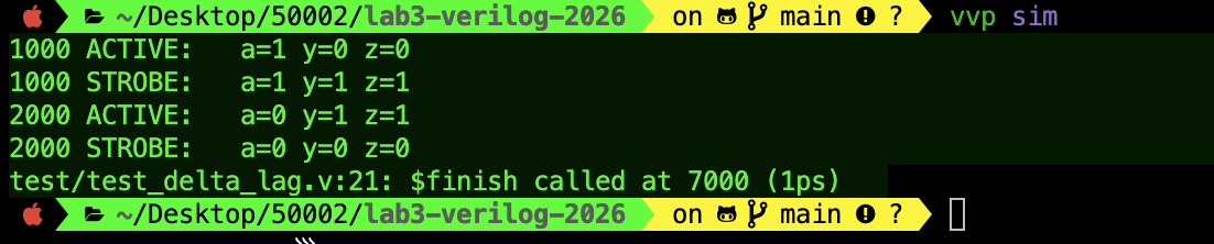
You should see the following printout:
And the following waveform:
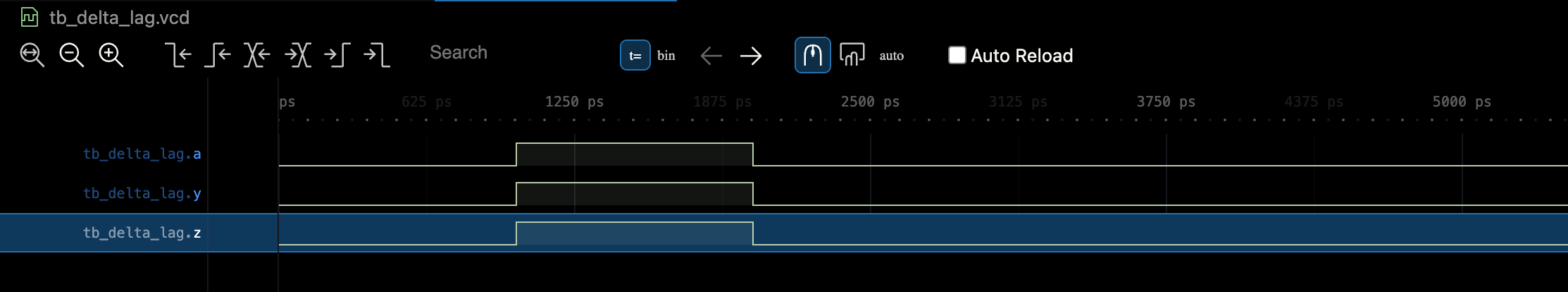
At first glance from the waveform, it looks like z, y follows a like any combinational device, but in simulation that’s not the case.
- When you do
#1 a = 1;,achanges in the active region at time 1ns, which triggers thealways @*block to run immediately. - But inside that block you used nonblocking assignments (
<=), soy <= a;andz <= y;do not updateyandzright away. - Instead, they are queued to update later in the same timestamp in the nonblocking-assign (NBA) region.
That is why $display prints a=1 y=0 z=0: you are observing the signals before the NBA updates have been applied.
$strobe prints at the end of the current time slot after NBAs have executed and the design has settled for that timestamp.
- By then, the queued update has made
ybecome 1.
That change can also retrigger the always @* block in another delta cycle, and z then follows.
- So the settled value at 1ns becomes
a=1 y=1 z=1, which is what$strobeshows. Same story whenagoes back to 0 at 2ns.
Is this “delta-lag” a problem?
Functionally, the settled values look combinational, so most waveforms and most simple tests will “pass,” which is exactly why this pattern is dangerous.
The issue is that your code no longer behaves like simple combinational logic at the level of delta cycles, and intermediate observations (some assertions, handshakes, or interacting always-blocks) can see the pre-NBA values and behave differently than you expect.
Hardware does NOT have delta cycles, so you are injecting a simulation artifact by using
<=in analways @*. With this, your simulation model is no longer a faithful combinational model while you are designing and verifying a larger system. It is the kind of dangerous misunderstanding that might cost you a lot in the future.
Breaking Ripple-Style Logic
Ripple-carry logic like the ripple-carry adder you made in the lab relies on immediate propagation of intermediate values. Nonblocking assignments prevent this within a single timestep.
Compare the correct and incorrect versions below:
// correct version

carry = ci;
for (i = 0; i < W; i = i + 1) begin
  s[i]  = a[i] ^ b[i] ^ carry;
  carry = (a[i] & b[i]) | (a[i] & carry) | (b[i] & carry);
end

// incorrect version
carry <= ci;
for (i = 0; i < W; i = i + 1) begin
  s[i]  <= a[i] ^ b[i] ^ carry;
  carry <= (a[i] & b[i]) | (a[i] & carry) | (b[i] & carry);
end
In the incorrect version, the carry does not propagate properly and simulation will produce incorrect sums.
Synthesis Inference vs Simulation Semantics
Synthesis tools infer flip-flops based on clock-edge patterns, not assignment operators. As a result, incorrect use of blocking assignments in clocked logic may still synthesize correctly while simulating incorrectly.
Here we attempt to set d as q in always @(posedge clk) block.
always @(posedge clk)
  q = d;
| Expected Hardware Intent | Observed Simulation Risk |
|---|---|
| Single D flip-flop | Interaction with other registers may be incorrect |
| Pipeline collapse or ordering errors may occur |
It might still be synthesized as a single DFF on hardware, BUT synthesis success does not validate RTL correctness. Simulation semantics must reflect hardware intent, otherwise you might run into problems when you test fails somewhere in the larger system due to such technical debt.
Multiple Always Blocks Driving the Same Register is Illegal
Assigning the same register in multiple always blocks creates multiple drivers, which is illegal or ambiguous in synthesis and simulation.
This is incorrect:
always @(posedge clk) if (a) q <= 1;
always @(posedge clk) if (b) q <= 0;
| Expected Hardware Intent | Observed Behavior |
|---|---|
| Undefined | Simulator-dependent resolution |
| Likely synthesis error |
Each register must be assigned in exactly one procedural block
Multiple Nonblocking Assignments to the Same Register in the Same Block is Confusing
Within a single procedural block, multiple nonblocking assignments to the same register result in the last executed assignment determining the final update for that timestep. This is like adding a MUX in the d port of the dff but the following code hides the MUX from the untrained eye:
always @(posedge clk) begin
  q <= 1'b0;
  if (a) q <= 1'b1;
end
| Expected Hardware Intent | Observed Simulation Behavior |
|---|---|
| Conditional assignment | If a == 1, the second assignment overrides the first |
While legal (compiles and run in simulation without error, and also synthesise without error), this pattern can obscure intent and should be used sparingly.
A better way is writing in a single line:
always @(posedge clk) begin
  q <= a ? d1 : d0;
end
Or writing explicit if-else or case:
// using if-else
always @(posedge clk) begin
  if (a) q <= d1;
  else   q <= d0;
end

// using case
always @(posedge clk) begin
  case (sel)
    2'b00: q <= d0;
    2'b01: q <= d1;
    2'b10: q <= d2;
    default: q <= d3;
  endcase
end
The neatest way would be to separate the combinational next-state MUX from the register:
reg q_d;

// combinational part
always @* begin
  q_d = d0;
  if (a) q_d = d1;
end

// sequential part
always @(posedge clk) begin
  q <= q_d;
end
Latch Inference Is Independent of Assignment Operator
As you saw in Lab 3, latch inference occurs when a combinational block does not assign an output on all control paths. This is unrelated to the choice of = or <=.
This is an example of latch being inferred in a combinational logic as not all paths result to a legal output y:
always @* begin
  if (sel) y = a;
end
The corrected version is:
always @* begin
  y = b;
  if (sel) y = a;
end
Testbench Races at Clock Edges
Testbenches that drive inputs or sample outputs exactly on a clock edge may introduce artificial races.
Here’s a risky pattern to write in a testbench: when we change d right at the posedge of the clk in edge-triggered dff DUT (rising edge):
// DUT samples d on posedge clk
always @(posedge clk) q <= d;

// TB also drives d on posedge clk (race with DUT sampling)
always @(posedge clk) d = $random;
Both blocks trigger on the same edge, and the Verilog standard does not guarantee which “happens first” across different always blocks. So the value captured into q can become tool- or run-dependent.
A safer pattern would be to introduce a slight delay:
// Option A: change inputs on the opposite edge
always @(negedge clk) d = $random;
// Option B: change inputs a tiny time after the edge (still same cycle, but not same instant)
always @(posedge clk) #1 d = $random; // 1 time unit (here 1ns/1ps timescale matters)
// Option C: drive with a periodic delay that is not aligned to posedge
initial begin
  d = 0;
  forever #7 d = ~d; // for a 10ns clock, this will not land exactly on posedges
end
# delays are fine in testbenches (they are not synthesizable RTL), and the goal is simply to not drive or sample signals at the exact same instant as the DUT’s clock edge unless you are deliberately testing setup/hold violations.
Issues on Using Blocking Assignment in a Clocked always @(posedge clk) Block
A clocked always @(posedge clk) block executes only at rising clock edges. Therefore, whether blocking (=) or nonblocking (<=) assignment is used, the left-hand side signal changes only at clock edges and holds its value between edges. In that limited sense, both operators appear to produce “the same effect.”
However, they are not equivalent in simulation semantics at the clock edge. The distinction is:
- Blocking (
=) updates the target immediately during the execution of the clocked block at thatposedge. - Nonblocking (
<=) schedules the update to occur after all clocked blocks have evaluated for that timestep, modeling simultaneous register updates.
This difference is invisible in trivial single-register examples, but becomes critical as soon as multiple registers interact.
Single Register Assignment: Appears Equivalent
This is the blocking version:
module dff_blocking(
  input  wire clk,
  input  wire rst,
  input  wire d,
  output reg  q
);
  always @(posedge clk or posedge rst) begin
    if (rst) q = 1'b0;
    else     q = d;
  end
endmodule
This is the non-blocking version:
module dff_nonblocking(
  input  wire clk,
  input  wire rst,
  input  wire d,
  output reg  q
);
  always @(posedge clk or posedge rst) begin
    if (rst) q <= 1'b0;
    else     q <= d;
  end
endmodule
| Aspect | Description |
|---|---|
| Expected Hardware Intent | A D flip-flop with optional reset |
| Observed Simulation Behavior | q updates only on rising edges |
| Between Clock Edges | q holds its value |
| Practical Outcome | Waveforms will usually match in this isolated single-register case |
This is the origin of the misconception that blocking in a posedge block “is the same” as nonblocking.
Consider the following testbench:
`timescale 1ns/1ps
module tb_single_dff_equivalence;

  reg clk, rst, d;
  wire q_b, q_nb;

  dff_blocking    u_b  (.clk(clk), .rst(rst), .d(d), .q(q_b));
  dff_nonblocking u_nb (.clk(clk), .rst(rst), .d(d), .q(q_nb));

  initial begin
    clk = 0;
    forever #5 clk = ~clk;
  end

  initial begin
    $dumpfile("tb_single_dff_equivalence.vcd");
    $dumpvars(0, tb_single_dff_equivalence);

    rst = 1; d = 0;
    #12 rst = 0;

    #3  d = 1;
    #10 d = 0;
    #10 d = 1;

    #30 $finish;
  end

endmodule
Both waveforms q_b and q_nb will typically be identical, but we know that it is not right in principle to use a blocking assignment in a clocked block especially when you’re trying to implement sequential logic. The next section shows the flaw of this approach.
Two Registers in the Same Clocked Block: Blocking Changes the Meaning
This code uses blocking assignments, so the order of assignment is dependent:
module two_stage_blocking(
  input  wire clk,
  input  wire rst,
  input  wire d,
  output reg  q1,
  output reg  q2
);
  always @(posedge clk or posedge rst) begin
    if (rst) begin
      q1 = 1'b0;
      q2 = 1'b0;
    end else begin
      q1 = d;
      q2 = q1;
    end
  end
endmodule
While this code uses nonblocking and the order no longer matters since assignment is simultaneous:
module two_stage_nonblocking(
  input  wire clk,
  input  wire rst,
  input  wire d,
  output reg  q1,
  output reg  q2
);
  always @(posedge clk or posedge rst) begin
    if (rst) begin
      q1 <= 1'b0;
      q2 <= 1'b0;
    end else begin
      q1 <= d;
      q2 <= q1;
    end
  end
endmodule
The expected hardware intent is to have two flip-flops in series. The defining behavior is:
q1(t+1) = d(t)q2(t+1) = q1(t)(one additional cycle delay)
However, here’s what we got in simulation using the testbench below:
- With nonblocking,
q2is a two-edge delayed version ofd(correct). - With blocking,
q2reads the newly writtenq1in the same timestep, collapsing the pipeline stage in simulation.
`timescale 1ns/1ps
module tb_two_stage_difference;

  reg clk, rst, d;
  wire q1_b, q2_b;
  wire q1_nb, q2_nb;

  two_stage_blocking    u_b  (.clk(clk), .rst(rst), .d(d), .q1(q1_b),  .q2(q2_b));
  two_stage_nonblocking u_nb (.clk(clk), .rst(rst), .d(d), .q1(q1_nb), .q2(q2_nb));

  initial begin
    clk = 0;
    forever #5 clk = ~clk;
  end

  initial begin
    $dumpfile("tb_two_stage_difference.vcd");
    $dumpvars(0, tb_two_stage_difference);

    rst = 1; d = 0;
    #12 rst = 0;

    // toggle d between edges for clarity
    #3  d = 1;
    #10 d = 0;
    #10 d = 1;
    #10 d = 0;

    #40 $finish;
  end

endmodule
Waveform expectation:
q2_nbtrailsdby two rising edges.q2_btrailsdby one rising edge.
This demonstrates that blocking in a clocked block is not equivalent once there is register-to-register dependence.
Race Conditions Across Multiple Clocked Always Blocks
This code uses blocking assignment in a separate clocked blocks:
module two_always_blocking_race(
  input  wire clk,
  input  wire rst,
  input  wire d,
  output reg  q1,
  output reg  q2
);
  always @(posedge clk or posedge rst) begin
    if (rst) q1 = 1'b0;
    else     q1 = d;
  end

  always @(posedge clk or posedge rst) begin
    if (rst) q2 = 1'b0;
    else     q2 = q1;
  end
endmodule
We initially expect a flip-flops in series, so q2 should consistently lag q1 by one cycle.
However in simulation, because both blocks trigger at the same posedge, simulator scheduling order matters:
- If block 1 executes first:
q2may see the newq1. - If block 2 executes first:
q2sees the oldq1.
This is nondeterministic in principle. Some simulators appear consistent but this should not be relied upon.
The correct modeling using nonblocking assignment ensures both registers sample old values and update together.
always @(posedge clk) q1 <= d;
always @(posedge clk) q2 <= q1;
If you write a testbench for the module above and your still looks “stable” run-to-run, that is also normal: many simulators use a consistent internal ordering, so you may not see it flip every run. The point is that the result is not guaranteed by the language when you write it this way, so it is fragile across tools, versions, or when you add more logic.
Summary
Blocking assignment inside always @(posedge clk) can appear equivalent to nonblocking assignment only in isolated, single-register situations. The equivalence breaks immediately when:
- A clocked block updates multiple registers with data dependencies, or
- Multiple clocked blocks interact at the same clock edge.
In these common cases, blocking assignment introduces order dependence and/or race conditions in simulation that do not match the simultaneous update behavior of real flip-flops.