 50.002 CS
50.002 Computation Structures
Information Systems Technology and Design
Singapore University of Technology and Design
Beta CPU Diagnostics
Detailed Learning Objectives
- Implement Interrupt Handling in Beta CPU
- Describe the types of interrupts in the Beta CPU: synchronous (software-driven) and asynchronous (hardware-driven) interrupts.
- Examine how interrupts are sampled and processed within the CPU’s control system to ensure timely and correct response to external and internal events.
- Diagnose Faults in the CPU Datapath
- Develop skills in identifying and diagnosing faults within the Beta CPU’s datapath using diagnostic software tools.
- Explain how to use simple test programs to isolate and identify specific faulty components within the CPU.
- Implement Fixes for Faulty Datapaths
- Design strategies for making code adjustments and changes to bypass or correct faulty components within the Beta CPU’s architecture.
- Experiment with altering CPU behavior through modifications in the control logic to handle specific types of errors or malfunctions.
These objectives aim to equip us with the ability to not only understand the inner workings of the Beta CPU but also to effectively address and resolve issues that may arise during its operation, especially those related to the CPU’s datapath and control mechanisms.
In this chapter, we’ll focus on understanding and fixing problems in the Beta CPU, specifically looking at its datapath. We’ll learn how to find out which datapath might be faulty using simple testing software to spot these issues, and figure out what code changes can help when parts of the system aren’t working correctly. Our goal is about getting to know the Beta CPU datapath better and being able to fix it whenever possible. We will also learn how to handle interrupts in Beta datapath.
Interrupt Handling
Interrupts; as the name suggests is a response initiated by the CPU when an error or out-of-the-ordinary event occurs.
\(\beta\) interrupts come in two broad categories: synchronous and asynchronous interrupts. The key difference lies in their timing and source.
- Synchronous Interrupts (also known as exceptions or software interrupts)
- Asynchronous Interrupts (also known as hardware interrupts)
Take it Easy
We will learn about this more in the final weeks of 50.002 and in 50.005.
Sampling the IRQ Signal
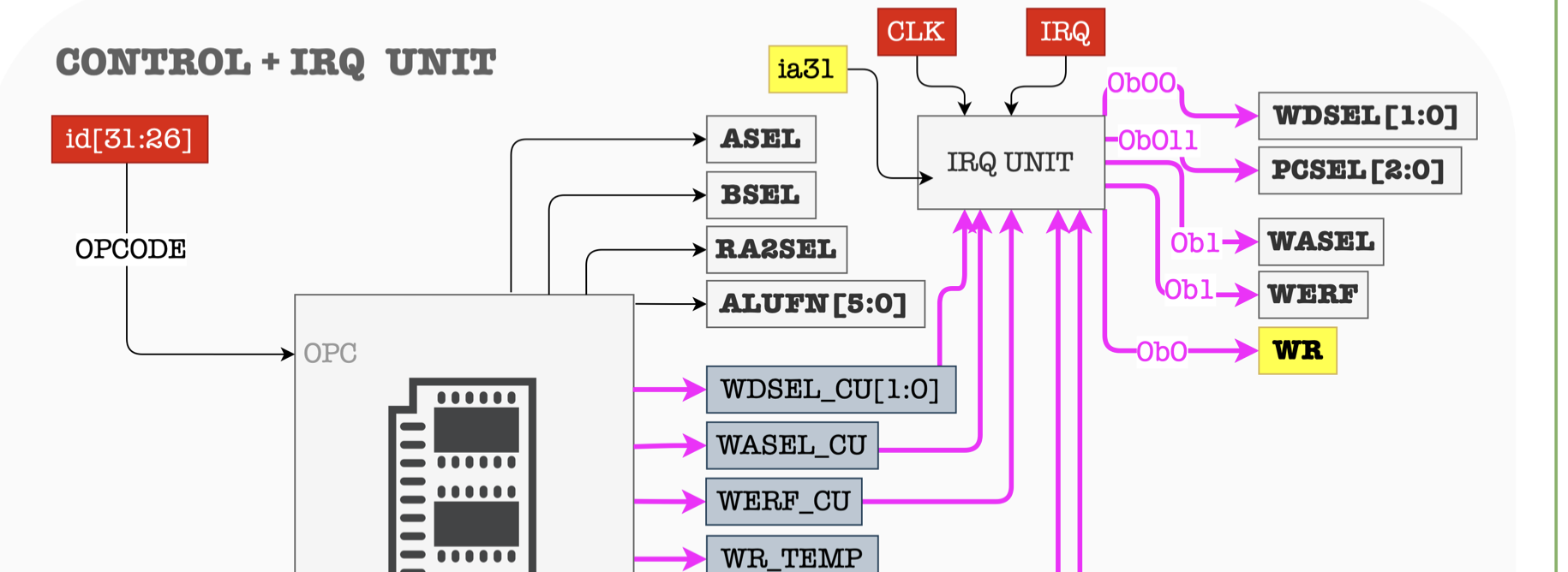
Notice the presence of CLK signal at the IRQ (interrupt) unit. This unit samples the incoming IRQ signal. We need to sample and synchronize it with the CPU clock because the IRQ signal actually an asynchronous interrupt trigger. In the later weeks, we will learn that asynchronous interrupts are generated by other hardware devices at arbitrary times with respect to the CPU clock signals. Therefore, we need another sequential logic device to condition/synchronize it such that it doesn’t cause unwanted changes to the Control Unit in the middle of execution (in the middle of a clock cycle).
This sampling device that receives the external IRQ signal allows the CPU to sample the input IRQ signal during the beginning of each instruction cycle, and will respond to the trigger only if the signal IRQ is asserted when sampling occurs.
The presence of the CLK signal in the Beta Datapath is written to remind you that the CPU should be able to sample the asynchronous IRQ signal for each clock cycle. However, the heart of the Control Unit itself is combinational logic device (e.g: ROM) and not a sequential one.
Synchronous Interrupts: Traps and Faults
Synchronous interrupts (or sometimes known as exception, or software interrupt) interrupts that are generated by the CPU itself as a result of executing an instruction. They’re also called software interrupts in some books. There are two types of synchronous interrupts:
- System Calls (Traps): A system call is a mechanism used by an application program to request service from the operating system. When a system call is made, the CPU switches to kernel mode to execute the operating system’s code. This is often referred to as a “trap,” as the application is effectively trapping into the operating system.
- Faults: Faults are a type of exception raised by the CPU in response to error conditions, like a division by zero, invalid memory access, or other illegal operations. When a fault occurs, the CPU switches to kernel mode to handle the error, potentially terminating the offending process or taking other corrective actions.
Traps (intentional) and faults (unintentional) falls under the category of synchronous interrupts becauase they are synchronous with the CPU clk cycle. They are both the outcome of executing illegal instructions, i.e: when we supply an illegal OPCODE. Such illegal opcode does not correspond to any of the instructions defined in the ISA.
The difference between traps and faults lie in its intention: traps are intentional while faults are not.
The datapath that handles trap/fault (due to Illegal OPCODE) is as follows:

Asynchronous Interrupts: Hardware Interrupts
Asynchronous Interrupts are interrupt signals that come from outside the CPU’s current execution stream (not synchronysed with CPU clock). They are not directly tied to the execution of the current instruction sequence. These are signals sent to the processor from external devices, like a mouse or keyboard. When the CPU receives an interrupt, it temporarily halts the current execution thread, saves its state, and switches to kernel mode to handle the interrupt. After handling the interrupt, the CPU can return to the previous state and continue execution.
When hardware interrupts occur, it would require the CPU to “pause” the execution of the current program and handle the interrupt.
- At the beginning of each cycle, the CPU will always check whether
IRQ == 1. - If
IRQ != 1, the CPU will continue with normal execution. - If
IRQ == 1, the CPU will pause the current execution and handle the interrupt request first (and eventually resume back the paused execution after the interrupt handling is done).
The datapath that handles interrupt (due to asynchronous IRQ signal) is as follows:
Differences in Datapath: Async vs Sync Interrupts (simplified)
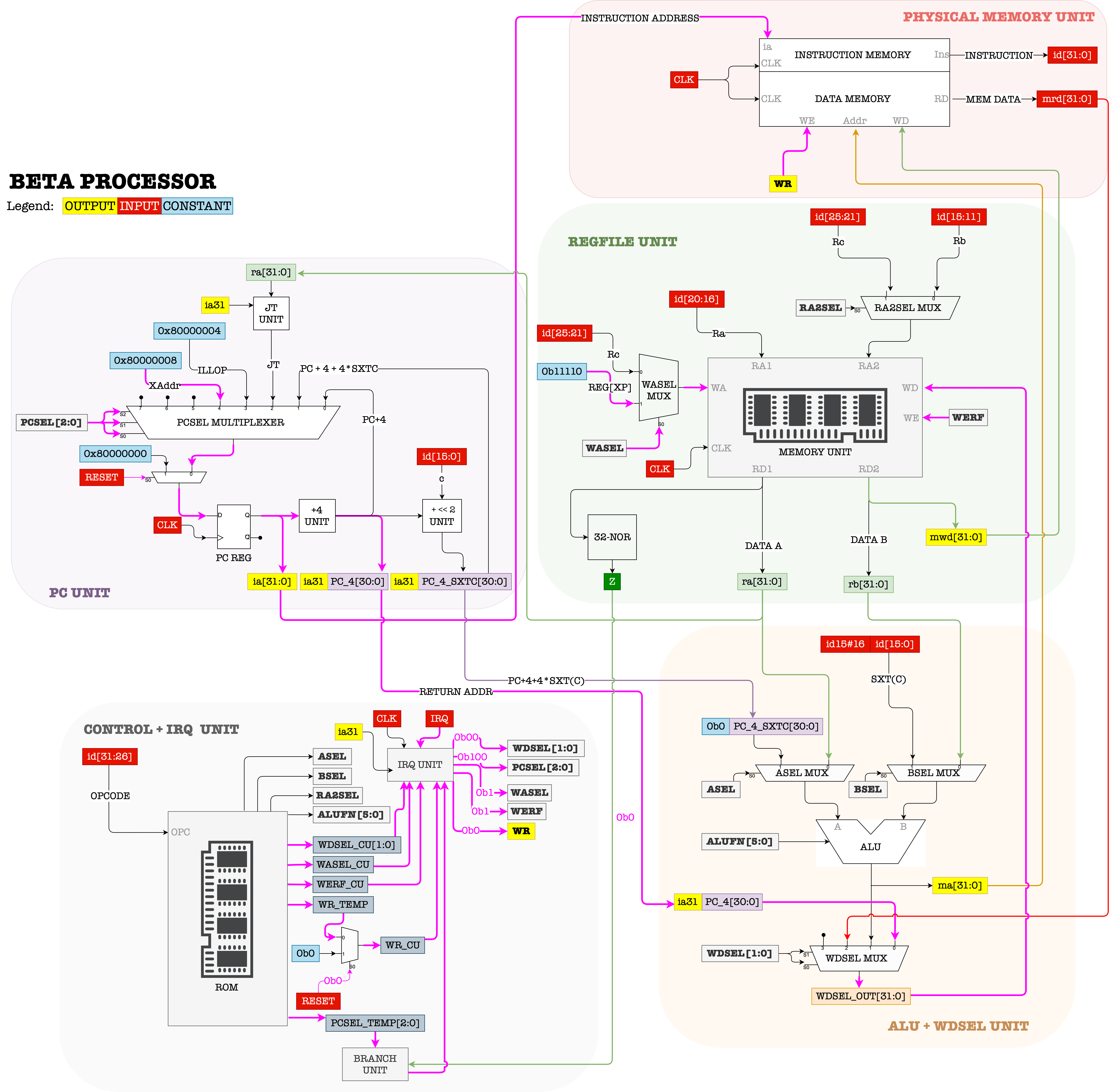
There’s only one difference between the two types of interrupts (async vs sync): the datapath at the PCSEL MUX.
The PCSEL multiplexer’s fourth and fifth input are called ILLOP and XAdr. In \(\beta\) ISA,
ILLOPis set at0x80000004XAdris set at0x80000008
In this address resides the entry point of program that handles these events: illegal operation or hardware interrupts.
Control Signals for Interrupts
ALUFN = --WERF = 1BSEL = --WDSEL = 00WR = 0RA2SEL = --PCSEL:Illegal_Opcode ? 011 : 000IRQ ? 100 : 000
ASEL = --WASEL = 1
Register XP (R30)
During interrupts, we set
WASEL = 1andWDSEL = 00andWERF = 1.PC+4(supposed next instruction’s address) is then stored atReg[XP](register 30, or11110in binary) so that we may resume the execution of this currently interrupted program once the interrupt has been handled.
Fault Detection and Diagnostics
In the realm of computer engineering, particularly when dealing with the intricacies of CPU hardware, the process of detecting and isolating faults within the CPU datapath is a critical task. For instance, if the RA2SEL MUX is faulty, then any ST instructions will be affected.
Our objective is to create straightforward test programs specifically designed to identify particular faults. These programs are essential and should be capable of altering the state of the CPU and/or Memory in a distinct manner if such faults are present. Prior to initiating this process, it’s crucial to have a clear understanding and reference of the control logic signals:

You should always begin with some assumptions, e.g: initial contents of all registers in the regfile are 0, or that the Memory state from certain address range is of certain values (depending on the question), and then design some diagnostic program with a known end state of regfile and/or Memory. You then must run the program for a fixed amount of CPU clk cycle and observe the differences in the state of the regfile and/or Memory to what you should expect in a fully functional Beta CPU.
Example: RA2SEL MUX is faulty
Suppose you suspected that the RA2SEL MUX might be faulty:
- The MUX always “sees” that the
RA2SELsignal given is always stuck at0 - It cannot be
1even if the Control Unit gives outRA2SELsignal of1
- The values in the
PC/ Registers in Regfile / Memory Unit will be different from a working Beta CPU if these programs were to be executed in this faulty Beta.- You can be 100% sure the discrepancy is caused by
RA2SELMUX being faulty and not any other faults (isolation)
Suppose we assume the initial content of all registers are 0 for this exercise, and that PC starts from 0. This condition might differ depending on the question’s scenario, so read them carefully. Since only ST instruction requires RA2SEL signal to be 1, our program must utilise ST instructions.
Consider following program P1, to be run at exactly 3 clk cycle (or until HALT(), whichever comes earlier):
.=0x0000
LDR(constant, R0)
ST(R0, answer, R31)
HALT()

constant: LONG(8)

.=0xFFFC
answer: LONG(4)
In a fully working Beta CPU, we should observe that constant 8 is stored in Memory address 0xFFFC (as the content Mem[answer]). However, if the RA2SEL MUX is faulty as described above, we will see that the content of R31 (which is 0) will instead be stored into Mem[answer].
Explanation:
- The 16-bit signed constant of the
STinstruction is0xFFFC - This makes bit 15 to 11 to be
11111(what we deems as ‘Rb’) - If
RA2SELMUX selects input0during this instruction, it will take the content of register11111(R31) to be stored atMem[answer] - Therefore we will observe
0atMem[answer]instead of8
Now consider the following program P2 to be run at exactly 3 clk cycle (or until HALT(), whichever comes earlier):
.=0x0000
LDR(constant, R0)
ST(R0, answer, R31)
HALT()

constant: LONG(8)

.= 0x07FC
answer: LONG(4)
P2 will not be able to detect the faulty in RA2SEL MUX because we would have the value 8 stored at Mem[answer] regardless of whether the RA2SEL MUX is faulty or not.
Explanation:
- The 16-bit signed constant of the
STinstruction is0x07FC, therefore bit 15 to 11 is now00000instead of11111 - This means that we are still storing the content of
R0to addressanswer - Since both bit 25 to 21 (Rc) and bit 15 to 11 (Rb) are identical (
00000), it does not matter if theRA2SELMUX selected Rc or Rb
Example: ASEL MUX is faulty
Suppose you suspected that the ASEL MUX might be faulty:
- if
ASEL = 0, the output is always 0. - There’s no problem if
ASEL = 1.
Similarly, note that:
- The values in the
PC/ Registers in Regfile / Memory Unit will be different from a working Beta CPU if these programs were to be executed in this faulty Beta.- You can be 100% sure the discrepancy is caused by
ASELMUX being faulty and not any other faults (isolation)
Similarly, we assume the initial content of all registers are 0 for this exercise and that PC starts from 0.. We need to write a diagnostic program that requires ASEl=0. This involves all Type 1 arithmetic operation. Consider the following program P3 to be run at exactly 4 clk cycle (or until HALT(), whichever comes earlier):
.=0X000
CMOVE(8, R1)
CMOVE(8, R2)
MUL(R1, R2, R0)
HALT()
The program above can easily detect if the ASEL MUX is faulty as described by observing the content of R0 when the program halts. If the Beta CPU is faulty, the content of R0 will be 0. Otherwise, it will be 64.
Explanation:
- If the
ASELMUX is faulty, we are multiplying the content of R2 with0instead of the content ofR1 - Hence, the result stored at
R0will be 0
Now consider the following program P4, to be run at exactly 4 clk cycle (or until HALT(), whichever comes earlier):
.=0X000
CMOVE(5, R1)
LDR(constant, R2)
MUL(R1, R2, R0)
HALT()

constant: LONG(0)
P4 will not be able to detect the fault because the content of R0 will be 0 regardless, because Mem[constant] that’s loaded to R2 is 0 anyway, and anything multiplied by 0 will have the value of 0.
Example: BOTH ASEL & RA2SEL MUXes are faulty
Now let’s try and combine both scenarios where both the ASEL and RA2SEL MUXes are simultaneously faulty as described above, and you don’t want to waste your time loading and running multiple programs and would like to select one that can detect both faults.
- You can be 100% sure the discrepancy is caused by both
RA2SELsignal orASELMUX faulty.- Programs that can only detect the
RA2SELsignal faulty but notASELmultiplexer faulty (or vice versa) is not acceptable.
As usual, you can assume that the initial content of all registers are 0 and that PC starts from 0. To detect both faults at once, we need a program that utilises ST as well as Type 1 arithmetic operations that will alter register or memory contents differently than a fully functional Beta CPU.
Consider the following program P5 (run for 5 clk cycle):
.=0x000
LDR(constant, R0)
LDR(constant + 4, R1)
ADD(R0, R1, R2)
ST(R2, constant + 8, R31)
HALT()

constant: LONG(8)
LONG(4)
The content at Mem[constant+8] will be 8 instead of 12 if only the RA2SEL MUX is faulty, and the content stored at R2 will be 4 instead of 12 if only the ASEL MUX is faulty.
Explanation:
- If the
ASELMUX is faulty, we will be adding0(instead of the content ofR0which is8) with the content ofR1(which is4) and storing it atR2. The content ofR2 = 0 + Reg[R1] = 4instead of the expected12. constantis equivalent to address20, or0x0014. This makes bit 15 to bit 11 of theSTinstruction to be00000- If
RA2SELMUX is faulty, we will be storing the content ofR0(which is8) instead of the content ofR2(which might be 4 or 12 depending on whetherASELMUX is faulty)
Now consider another program P6, to be run for 5 clk cycles:
.=0x0000
ADDC(R31, 5, R0)
ST(R0, constant + 8, R31)
LDR(constant, R1)
ADD(R1, R1, R2)
HALT()

.=0x0BCC
constant: LONG(8)
LONG(4)
Will P6 be able to detect both faults simultaneously? Why or why not?
Yes, P6 will be able to detect both faults at the same time:
- The content of
R1is stored toMem[Constant+8]instead of the content ofR0. Therefore,Mem[Constant+8]is0instead of5. - The content of
R2is8instead of16.
Finally, consider program P7 below (to be run for 6 clk cycle or until HALT()):
.=0x000
constant: LONG(8)
LONG(4)
LDR(constant, R0)
LDR(constant+4, R1)
ADD(R0, R1, R2)
ST(R1, .+8, R31)
HALT()
At first glance, the program above seems to be able to detect the faulties just fine. You might think the following:
- The content of
R2will be4instead of12if theASELMUX is faulty, and - The content of
Mem[28]will be8instead of4if theRA2SELMUX is faulty
However, since PC starts from 0, the first instruction that the CPU will attempt to execute will be LONG(8) and not LDR(constant, R0). This will trigger a software interrupt and therefore P7 will not be able to immediately isolate either of the faults.
Summary
This chapter on Beta CPU diagnostics are designed to provide us with comprehensive knowledge and skills in troubleshooting and resolving issues within the Beta CPU’s architecture, specifically focusing on the CPU’s datapath. It aims to equip us with the skills to not only understand the inner workings of the Beta CPU but also to effectively address and resolve operational issues, particularly those related to the CPU’s datapath and control mechanisms.
Here are the key points from this notes:
- Fault Detection and Diagnostics: To write test code that triggers certain datapaths suspected to be faulty. For instance, if the control unit is suspected to give a faulty PCSEL, instructions involving transfer of control (JMP, BEQ, BNE) are ideal to be used as test instructions.
- Complex Fault Diagnostics: If multiple faults are suspected to be present, the test code must be comprehensive such that it triggers all datapaths suspected to be faulty. Test code that is not comprehensive might give a false negative result.
- Interrupt Handling: Beta CPU handles both synchronous (ILLOP) and asynchronous (IRQ) interrupt. Both types of interrupts affect the flow of operations within the CPU. Special register XP is used to store the last interrupted address so that we can resume operation once the interrupt handler returns.
Diagnosing faults in Beta CPU datapath is not an easy task. It requires time and practice, not to mention that you must familiarise yourselves with Beta ISA in the first place. Head to our problem set for more exercise. In the problem set, we will take the diagnostics step further by thinking of alternative instructions that can be used to replace existing instructions affected by a particular faulty datapath.
Note that not all faults might have a replacement. For instance, if both ASEL and BSEL MUXes are faulty in the sense that both always output 0 regardless of the input or selector signals, then there’s no way to utilise the ALU anymore (which means: we can no longer compute arithmetic instructions anymore, rendering the CPU purposeless).