 50.002 CS
- Objectives
- Submission
- Starter Code
- Related Class Materials
- The Arithmetic Logic Unit (ALU)
- Task 1: Adder Unit
- Task 2: Compare Unit
- Task 3: Boolean Unit
- Task 4: Shifter
- Task 5: Multiplier
- Task 6: Assembling the ALU
- ALU Tester
- Operator Precedence
- Summary
- Checkoff
50.002 Computation Structures
Information Systems Technology and Design
Singapore University of Technology and Design
Lab 5: Arithmetic Logic Unit
Objectives
By the end of this lab, you should be able to:
- Design and implement a 32-bit combinational ALU using only logic gates, multiplexers, and adders, without relying on HDL math or comparison operators.
- Describe and implement how a single control signal (ALUFN) selects and programs multiple datapath behaviors within the ALU.
- Correctly generate and interpret the Z, V, and N condition codes, and understand how they are later reused by comparison and control-flow logic.
- Construct and validate the five major ALU sub-units:
- Adder / subtractor
- Comparator
- Boolean logic unit
- Shifter
- Multiplier (low 32 bits)
- Assemble these sub-units into a single ALU using clean datapath selection logic.
- Design manual and automated testers that validate correctness both in simulation and on FPGA hardware.
- Connect ALU behavior back to the Beta ISA, understanding how instructions drive datapaths through control signals rather than hardwired logic.
Submission
All ALU related marks are collected during your scheduled 1D Project Checkoff 1: ALU slot with your Cohort TA. During this single session you will show both the Lab 5 work and the 1D project ALU work.
Marks breakdown:
- Lab 5 implementation checkoff (2%): group
- Show that your ALU passes the required testbenches.
- Show a working manual and automated ALU tester in the simulator.
- Lab 5 questionnaire on eDimension (2%): individual
- 1D Project Checkoff 1: ALU (3%): group
- Show a working manual and automated ALU tester on the FPGA hardware.
Unless otherwise stated, ALU checkoff marks are awarded per 1D project group, not per individual. ALL team members should attend the checkoff slot.
Starter Code
Please clone the starter code from this repository, then open it with Alchitry Lab V2.
git clone https://github.com/natalieagus/50002-lab-alu.git
Related Class Materials
The lecture notes on Logic Synthesis and Designing an Instruction Set are closely related to this lab.
This lab deepens your understanding of how specific logic functions are physically constructed, and how those circuits are made programmable using control signals rather than hardware changes. By the end of this lab, you should clearly understand how one ALU can support many operations purely through combinational logic and control.
| Lecture Section | How It Connects to This Lab |
|---|---|
| Logic Synthesis: N-input Gates | Forms the foundation of all ALU sub-units. You will explicitly build adders, comparators, boolean logic, and multipliers using basic gates instead of relying on HDL operators. |
| Logic Synthesis:Special Combinational Logic Devices | Directly applied in this lab for building multiplexers, cascading them into wider datapaths, and selecting ALU outputs. |
| Instruction Set: Programmable Control Systems | Explains how a single piece of hardware can perform multiple operations using control signals. This is exactly how ALUFN programs your ALU to switch between ADD, SHIFT, MUL, COMPARE, and BOOLEAN operations. |
The Arithmetic Logic Unit (ALU)
In this lab, we will build a 32-bit arithmetic and logic unit (ALU) for the Beta processor using logic gate primitives. This is part of your 1D project. You WILL need the ALU for your 1D Project and also following Lab (Beta CPU).
Arithmetic Logic Unit (ALU)
The ALU is a combinational logic device that has two 32-bit inputs (which we will call “A” and “B”) and produces one 35-bit output:
alu[31:0],Z,V, andN. We will start by designing the ALU modularly. It is composed from five as a separate modules, each producing its own 32-bit output. We will then combine these outputs into a single ALU result.
In this lab, we will attempt to create a 32-bit ALU. It is one of the components inside our Beta CPU. We will eventually utilise our work here to build an entire Beta CPU circuit in the next lab.
The Arithmetic Logic Unit (ALU) serves as the central core of the CPU, handling a variety of logical computations. Essential operations that a standard ALU encompasses are:
- An Addition/Subtraction Unit, facilitating elementary addition and subtraction tasks.
- A Comparison Unit, utilized for branching functions.
- A Boolean Unit, dedicated to boolean operations such as XOR, bit masking, and similar tasks.
- A Shifter Unit, instrumental in operations like division or multiplication by 2, as well as segmenting data.
- A Multiplier Unit, specialized in performing multiplication. The design of this unit is more complicated than the rest of the units.
ALUFN vs OPCODE
Important: ALUFN != OPCODE
The
ALUFNsignal is NOT Beta CPUOPCODE, despite both being 6-bit long. These two encodings are NOT the same. TheALUFNis used to control the operation of the ALU circuitry, while the Beta CPUOPCODEis used by the Control Unit to control the entire Beta CPU datapath. In the next lab, you will build a ROM as part of the Control Unit that will translate theOPCODEfield of a currently executed instruction into the appropriateALUFNcontrol signal.
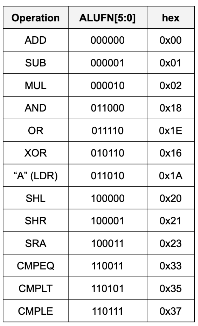
ALU Operations
The ALU can perform the following 13 arithmetic operations based on ALUFN signal given as an input:
ALU Implementation Requirement
You are NOT allowed to use any of Lucid’s math and comparison operators when implementing this lab’s ALU 13 functionalities. This is the requirement of your 1D project because we would like you to learn the basics and not solely rely on Vivado’s capability on creating components of the ALU. Please give the 1D project handout a read for further information.
Please follow the implementation of the units from the given schematics in this lab. For instance, you shouldn’t implement shifts (SHL, SHR, SRA) trivially using
>>and<<, and you shouldn’t implement ADD and SUB using+or-, etc. Instead you should create a ripple carry adder unit to implement ADD/SUB functionality, and create the shifter unit using multiplexers as shown in this handout.Failure to comply will result in -2% of your overall grades. However, you can use them for array indexing (bit selection) or checking conditions in loops.
However you are allowed to use boolean operators in an if-else clause only, for instance:
    // assume x, y are 32-bit signals
    sig x[32]
    sig y[32]

    if (x == y) // NOT allowed
    if (~|(x ^ y)) // DO this instead

    if (x == 2) // NOT allowed
    if (~|x[31:3] & x[1] & ~x[0]) // DO this instead
You can also use case statements as per usual.
For now there’s no reason you need to compute stuffs like x < 5 or x > 250 in this ALU component of your 1D project. For your 1D project, we will be using this ALU to perform addition, comparison, multiplication, bitwise boolean, and shifting.
Task 1: Adder Unit
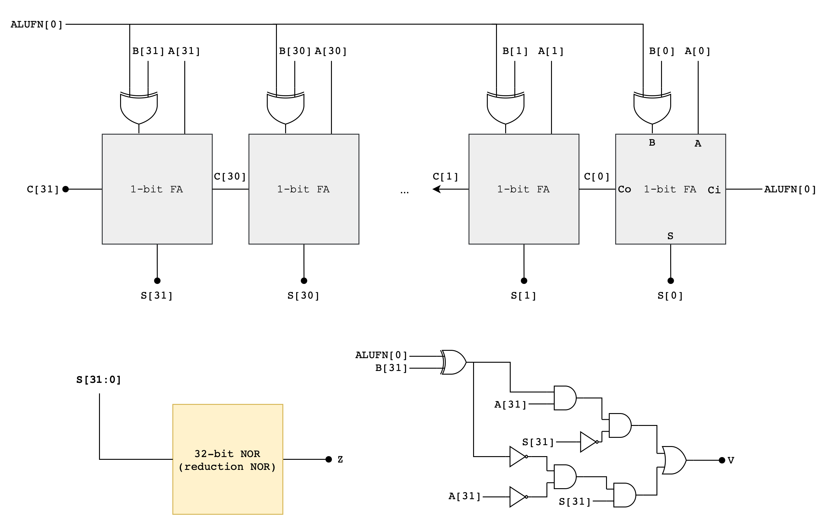
Implement an adder/subtractor unit that can add or subtract 32-bit two’s complement (SIGNED) inputs (A[31:0], B[31:0]). It should generate a 35-bit output: (S[31:0]) andZ, V, N signals. A[31:0] and B[31:0] are the 32-bit two’s complement (SIGNED) input operands and S[31:0] is the 32-bit signed output. Z/V/N are the three other output code bits described below:
Zwhich is true when the S outputs are all zero (i.e.,NOR(S) == 1 ? Z = 1 : Z = 0)Vwhich is true when the addition operation overflows (i.e., the result is too large to be represented in 32 bits), andNwhich is true when the S is negative (i.e.,S[31] == 1 ? N = 1 : N = 0).
Z, V, N will later be used by the comparator unit (read next section). The following diagram illustrates a suggested implementation of the 32-bit Adder/Subtractor Unit using a Ripple Carry Adder (RCA):
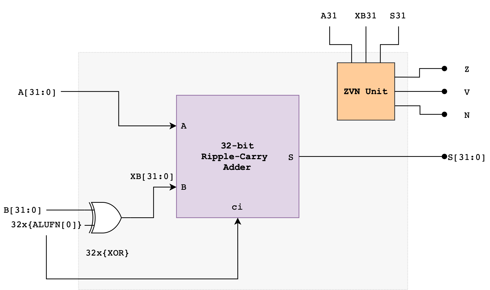
The ALUFN0 input signal controls whether the operation is an ADD or SUBTRACT. ALUFN0 will be set to 0 for an ADD (S = A + B) and 1 for a SUBTRACT (S = A – B). To perform a SUBTRACT, the circuit first computes the two’s complement of the B operand before adding the resulting value with A. The two’s complement of B is computed using the XOR gate and ALUFN0 as carry in to the first Full Adder in the RCA.
The Ripple Carry Adder
A Ripple Carry Adder (RCA) is a simple binary adder that consists of multiple full adders (FA) connected in series. It is used to add two binary numbers. You have met this device in the previous lab.
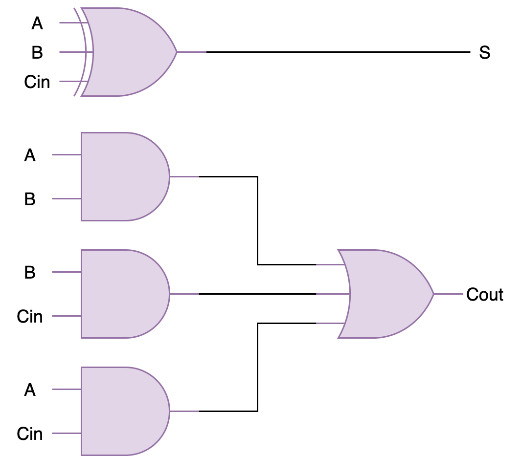
A full adder (FA) schematic is as shown:
To build a 32-bit RCA, you can connect 32 of these in series to form a 32-bit ripple-carry-adder. Below is an example of 4-bit ripple-carry-adder from the previous lab for your reference:
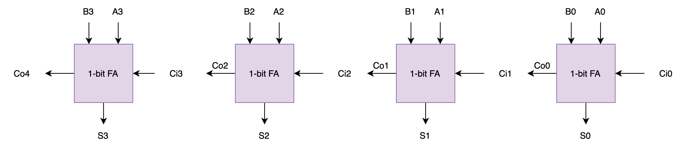
If you haven’t done it in the previous lab, you are encouraged to create the ripple carry adder as a standalone module that accepts the number of operands bits (e.g: SIZE) supported as the PARAMETERS.
Computing Overflow: V
What is overflow?
Overflow happens when the number of bits required to represent the signed result exceeds the hardware’s capability. There are two types of overflow: positive and negative.
Positive and negative overflow refer to specific types of integer overflow that occur when the result of an arithmetic operation exceeds the maximum or falls below the minimum value representable by a given number of bits for a signed integer type. This causes the value to “wrap around” to the opposite end of the range.
For example, consider a signed 4-bit adder. It can represent numbers from -8 to 7. If we let
a = 0111(7) andb = 0110(6) and add them together, it should result ins = 01101(13). However, since the hardware only supports 4-bit, we only see the result ass = 1101(-3). This is a positive overflow: where addition of two positive numbers yield a negative result.Now, can you come up with an example of negative overflow? That is where addition of two negative numbers yield a positive result.
Notice that overflow can never occur when the two operands to the addition have different signs. If the two operands have the same sign, then overflow can be detected if the sign of the result differs from the sign of the operands.
\[\begin{align*} V = &A_{31} \cdot XB_{31} \cdot \overline{S_{31}} + \overline{A_{31}} \cdot \overline{XB_{31}} \cdot S_{31} \end{align*}\]Note that we use XB, not B, that’s the output of the XOR gate (B XOR ALUFN[0]) shown in the adder schematic above.
Computing Overflow
VWhy is
Vcomputed like the above? Start by having a small example, let’s say a 4-bit RCA. If we haveA: 0111, andB: 0001, adding both values will result in a positive overflow. The true answer to this should be decimal8. With signed devices, we need 5 bits to represent decimal 8:01000. However since our RCA can only output 4-bits, we have our output as just1000, and this means decimal -8 in a signed 4-bit output. Now think about other possible overflow cases (negative overflow, etc).
Detailed Adder/Subtractor Schematic
Here’s the detailed schematic of the adder to get you started:
You may start by making a 1-bit Full Adder module first inside fa.luc, and then create a 32-bit RCA module in rca.luc. Afterwards, assemble everything inside adder.luc.
Implementation Tips
Remember that you are NOT allowed to use Lucid’s math operator, such as out = a+b or out = a-b to implement the adder unit. Please follow the implementation of the schematic above. This is part of the requirements of your 1D project. You can however use these operators for indexing.
repeat statement
Recall that the syntax of the repeat statement is as follows:
repeat(i, count, start = 0, step = 1) {
    statements
}
You can utilise repeat statement in Lucid V2 (the same applies for Verilog) to duplicate creation of multiple units of fa, like you did in the previous lab.
Remember that repeat statement in HDL (Hardware Design Language) like Lucid or Verilog does NOT perform the same way like the for loops we are familiar with in Python or Java. It’s important to understand that in HDLs, repeat loops/statements are used to describe hardware, not to control flow as in software programming. They primarily for generating repetitive hardware structures.
Reduction Operators
In HDLs, reduction operators applies the logic across the bits of the input to produce a single bit output. For instance, given a = 4b1010:
|a(reduction OR) is1|0|1|0, which is1&a(reduction AND) is1&0&1&01which is0^a(reduction XOR) is1^0^1^0which is0
Utilise your previously created RCA
It should be pretty straightforward to reuse the RCA created in your previous lab. You just need to add the XOR gates as well as the ZVN logic.
Test
Testbench
You can utilise the following testbench to test your adder’s functionality. Feel free to create your own.
testbench test_adder {
    adder adder(#SIZE(32))
    const TEST_CASES_ADDER = $reverse({
        // 1. basic add
        c{32d10,          32d3,           1b0, 32d13,          1b0, 1b0, 1b0},
        // 2. add to zero
        c{32d5,           -32d5,          1b0, 32d0,           1b1, 1b0, 1b0},
        // 3. negative result (no overflow)
        c{32d3,           -32d10,         1b0, -32d7,          1b0, 1b0, 1b1},
        // 4. positive overflow (max int + 1)
        c{32h7FFFFFFF,    32d1,           1b0, 32h80000000,    1b0, 1b1, 1b1},
        // 5. negative overflow (min int - 1)
        c{32h80000000,    32d1,           1b1, 32h7FFFFFFF,    1b0, 1b1, 1b0},
        // 6. subtraction resulting zero
        c{32d42,          32d42,          1b1, 32d0,           1b1, 1b0, 1b0},
        // 7. subtraction producing negative
        c{32d5,           32d8,           1b1, -32d3,          1b0, 1b0, 1b1},
        // 8. subtraction overflow (large negative minus positive)
        c{32h80000000,    32d1,           1b0, 32h80000001,    1b0, 1b0, 1b1}
    })

    test adderTest {
        repeat(i, 8){
            adder.a = TEST_CASES_ADDER[i][99:68]
            adder.b = TEST_CASES_ADDER[i][67:36]
            adder.alufn0 = TEST_CASES_ADDER[i][35]
            $tick()
            $assert(adder.s == TEST_CASES_ADDER[i][34:3])
            $assert(adder.z == TEST_CASES_ADDER[i][2])
            $assert(adder.v == TEST_CASES_ADDER[i][1])
            $assert(adder.n == TEST_CASES_ADDER[i][0])
            $print("PASS test case: %d", i+1)
        }
    }
}
$reverse
$reversefunction reverses the indices of the outer most dimension of expr. This is so thatTEST_CASES_ADDER[0]gives you test case 1 and not 8.
Manual Test (simulation)
Once you have implemented adder.luc, instantiate and connect its input and output properly in alu.luc so that we can test our adder unit manually.
    // alu.luc body
    adder.a = a;
    adder.b = b;
    adder.alufn = alufn;

    z = adder.z;
    v = adder.v;
    n = adder.n;

    alu_output = adder.out;
We have instantiated alu in tester_manual_alu for testing. tester_manual_alu is just an IO wrapper connected to alchitry_top so that we can have a more modular structure.
Be organised
You should not implement any logic in
alchitry_top, only I/O connections.
Use io_dip and/or io_button to key in arbitrary values of a, b and alufn, then observe the output at io_led and/or led. Utilise the knowledge you got from lab 2 to thoroughly test your adder before proceeding. If in doubt, consult your instructors/TAs or post questions on edstem.
Tester design suggestion:
- Since
aandbare 32-bit long and we only have 24 dip switches, you can create a tester FSM that allows us to store the first 16 bits ofa, then last 16 bits ofa, then first 16 bits ofb, and finally the last 16 bits ofb. - As for
alufnsignal, you can useio_dip[2][5:0]. - You can use
io_buttonto hold and peek low/high 16 bits alu output

This is a sample usage (negative overflow case):
- Set lower-16 bit A:
16h0usingio_dip[1:0], pressio_button[0]to latch, then set higher-16 A:16h8000similarly (this forms most negative number) - Afterwards set lower-16 B:
16h0then higher-16 B:16h8000from theio_dip[1:0](also most negative number) - Key in
alufnas5b0(+) fromio_dip[2][5:0] - Observed output: alu’s output is
32b0, zvn is110

Think of useful test cases, such as addition of zeroes, addition of two negative numbers, test overflow, subtraction of -ve values, and so on. You can see the testbench sample above when in doubt.
You are free to use a different interface if you wish.
Manual Test (Hardware)
Once it works on the simulator, you need to test it on hardware as well as sanity check. Do NOT delay test compilation.
Please be careful with the io dip switches, they’re delicate and easy to break. Use the tip of a male jumper wire to flick them.
Why don’t we just use the operators like + and -?
We made it a requirement in your 1D project to NOT use Lucid (or Verilog) math and comparison operators when implementing any of the 13 functionalities of the ALU. You can technically implement a 32-bit adder unit in this manner and let Vivado do the work:
module adder (
    input a[32],
    input b[32],
    input alufn0,
    output s[32]
  ) {

  always {
    if (alufn0){
      s = a + b;
    }
    else{
      s = a - b;
    }
  }
}
However the above does not allow you to learn anything new. Implementing components of the ALU from scratch has its own benefits as you’re still learning.
Firstly, it enables you to gain a deeper insight into the underlying hardware mechanisms that perform arithmetic operations, and offers a tangible perspective on how abstract mathematical concepts are translated into physical, operational circuits.
This hands-on experience is invaluable for developing an appreciation of the intricacies and challenges associated with digital circuit design, including considerations of timing, power consumption, and scalability.
Secondly, it encourages problem-solving skills, requiring you to apply logic and reasoning to create efficient and functional circuits, along with the first few weeks of 50.002 materials. This process enhances your ability to design, troubleshoot, and optimize digital systems, skills that are crucial for both academic and professional success in the CS field.
Finally, it cultivates an appreciation for the evolution of digital design methodologies and the role of automation in modern engineering. You are not learning how to rely on Vivado but rather to figure out how it works under the hood.
Task 2: Compare Unit
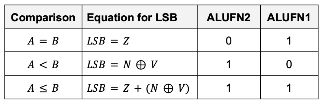
Implement a 32-bit compare unit that generate 1 bit output, depending on the following conditions:
The inputs to the compare unit are:
- The
ALUFNcontrol signals (used to select the comparison to be performed), in particular:ALUFN[2:1] - The
Z,V, andNbits. They’re the output of the adder/subtractor unit. The adder must be in subtraction mode.
Why should the adder be in subtraction mode? Discuss with your team members
Performance
What’s the tpd and tcd of the compare unit?
The Z, V and N inputs to this circuit can only be produced by the adder/subtractor unit. That means we need to first perform a 32-bit addition/subtraction between a and b before we can compare them. This means there’s some significant tpd to produce the output of the compare unit as the RCA is considerably slow.
In real life, you can speed things up considerably by thinking about the relative timing of Z, V and N and then designing your logic to minimize delay paths involving late-arriving signals. For instance, if you need to perform computations involving Z and other variables, you can compute those intermediary output involving the other variables first while “waiting” for Z. We do not need to worry much about it in this Lab as Vivado will do all sorts of optimisation for you.
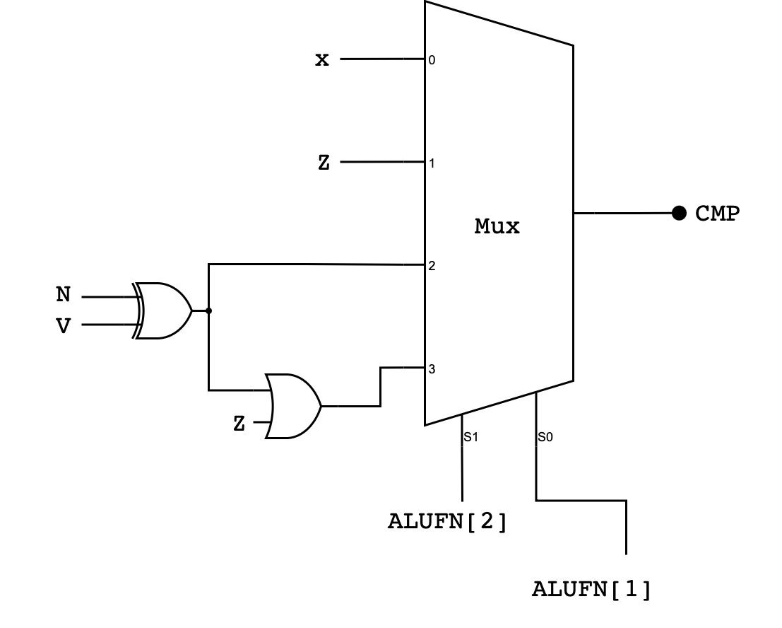
Detailed Compare Unit Schematic
Here’s the detailed schematic of the compare unit. Pay close attention to the bit selector and the corresponding inputs at the MUX:
Implementation Tips
Remember that you are NOT allowed to use lucid comparator directly to implement this unit. Basically, DO NOT do this:
// this is a working compare unit but illegal to use in 50002
module compare (
    input a[32],
    input b[32],
    input alufn[6],
    output cmp
) {

    always {
        cmp = 0
        if (alufn == b110011){
            cmp = a == b
        }
        else if (alufn == b110101){
            cmp = a < b
        }
        else if (alufn == b110111){
            cmp = a <= b
        }
    }
}
Reuse MUX2to1 and MUX4to1
You are highly encouraged to reuse the MUXes you created in the previous lab to implement the comparator unit. You can then utilise it inside compare.luc to implement the compare unit truth table above using signals Z, V, and N
Test
Testbench
testbench test_compare {
    compare compare
    const TEST_CASES_COMPARE = $reverse({
            // 1. CMPEQ true (z = 1)
            c{1b1, 1b0, 1b0, 2b01, 1b1},
            // 2. CMPEQ false (z = 0, v/n ignored)
            c{1b0, 1b1, 1b1, 2b01, 1b0},
            // 3. CMPLT true (n ^ v = 1, normal negative)
            c{1b0, 1b0, 1b1, 2b10, 1b1},
            // 4. CMPLT true (n ^ v = 1, overflow sign flip)
            c{1b0, 1b1, 1b0, 2b10, 1b1},
            // 5. CMPLT false (n ^ v = 0)
            c{1b0, 1b0, 1b0, 2b10, 1b0},
            // 6. CMPLE true via equality (z = 1)
            c{1b1, 1b0, 1b0, 2b11, 1b1},
            // 7. CMPLE true via less-than (n ^ v = 1)
            c{1b0, 1b0, 1b1, 2b11, 1b1},
            // 8. CMPLE false (greater-than)
            c{1b0, 1b0, 1b0, 2b11, 1b0}
        })

    test compareTest {
        repeat (i, 8){
            compare.z = TEST_CASES_COMPARE[i][5]
            compare.v = TEST_CASES_COMPARE[i][4]
            compare.n = TEST_CASES_COMPARE[i][3]
            compare.alufn = c{3b110,TEST_CASES_COMPARE[i][2:1], 1b1}
            $tick()
            $assert(compare.cmp == TEST_CASES_COMPARE[i][0])
            $print("PASS test case: %d", i+1)
        }
    }
}
Simulator and Hardware Test
As usual, do not forget to test it manually on the simulator as well as the hardware once your unit passes the testbench.
Since the alu must produce a 32-bit output, you should set the higher 31 bits to 0, and set the LSB to the output of the compare unit. You can use concatenation for this.
  // alu.luc body
  alu_output = c{31x{b0}, compare.cmp}; // concatenation
Your test cases must be comprehensive, and think of possible edge cases such as comparing two negative numbers together, or comparing zeroes.
It is very important to test each of your modules incrementally before proceeding to the next section. Debugging HDL is extremely difficult (no straightforward and convenient print statements or debugger to “pause” execution), so we shall minimise propagation of errors by testing each small module carefully.
Task 3: Boolean Unit
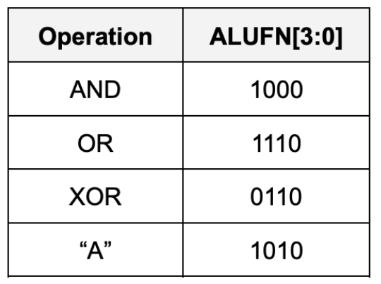
Implement a 32-bit Boolean unit that performs bitwise boolean operation between a and b. The unit should receive 32-bits of a and b as inputs, as well as 4-bit ALUFN[3:0] input, and produce a 32-bit output. In particular it should perform either AND, OR, XOR, or A bitwise boolean operations, depending on the ALUFN signals supplied:
Detailed Boolean Unit Schematic
Here’s the general schematic of the Boolean Unit:
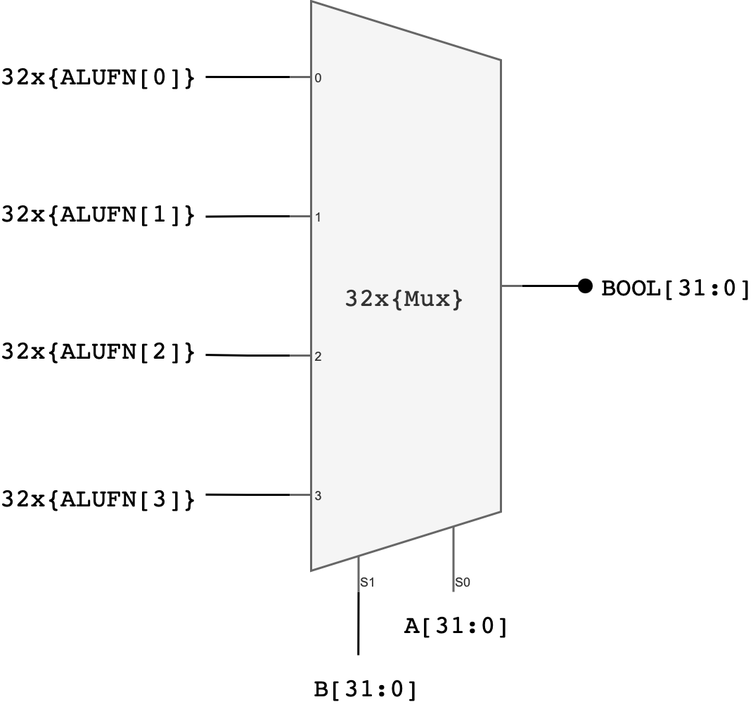
Explanation:
One possible implementation of a 32-bit boolean unit uses 32 copies of a 4-to-1 multiplexer where ALUFN0, ALUFN1, ALUFN2, and ALUFN3 hardcode the operation to be performed, and Ai and Bi are hooked to the multiplexer SELECT inputs. This implementation can produce any of the 16 2-input Boolean functions; but we will only be using 4 of the possibilities: AND, OR, XOR, and A.
In total, you should utilise 32 4-to-1 multiplexers to build the boolean unit. You can utilise the earlier created MUX_4.luc module to implement this.
Implementation Tips
You will need 32 copies of ALUFN signals as you will be plugging them into the input ports of each MUX_4. To do this, you can use the duplication operator in lucid, for instance:
// boolean.luc
  // module declaration

  // declaration of modules utilised in boolean unit
  MUX_4 MUX_4_32[32];

  always{
    // create 32 copies of ALUFN signal as input to each MUX_4 unit
    // the double curly brackets are intentional because
    // we are creating 2D array: 32 by 4 bits
    MUX_4_32.in = 32x{{alufn[3:0]}};
    // the rest of boolean.luc body

  }
Test
Testbench
testbench test_boolean {
    boolean boolean
    const TEST_CASES_BOOLEAN = $reverse({
            // 1. AND: basic mask
            c{32hFF00FF00,    32h0F0F0F0F,    4b1000, 32h0F000F00},
            // 2. AND: no common bits
            c{32hAAAAAAAA,    32h55555555,    4b1000, 32h00000000},
            // 3. OR: combine disjoint bits
            c{32hFF00FF00,    32h00FF00FF,    4b1110, 32hFFFFFFFF},
            // 4. OR: one side zero
            c{32h12345678,    32h00000000,    4b1110, 32h12345678},
            // 5. XOR: identical inputs cancel
            c{32hDEADBEEF,    32hDEADBEEF,    4b0110, 32h00000000},
            // 6. XOR: alternating bits
            c{32hAAAAAAAA,    32h55555555,    4b0110, 32hFFFFFFFF},
            // 7. A: pass-through ignores B
            c{32h12345678,    32hFFFFFFFF,    4b1010, 32h12345678},
            // 8. A: zero remains zero
            c{32h00000000,    32hDEADBEEF,    4b1010, 32h00000000}
        })

    test booleanTest {
        repeat (i, 8){
            boolean.a  = TEST_CASES_BOOLEAN[i][99:68]
            boolean.b  = TEST_CASES_BOOLEAN[i][67:36]
            boolean.alufn = c{2b01,TEST_CASES_BOOLEAN[i][35:32]}
            $tick()
            $assert(boolean.bool == TEST_CASES_BOOLEAN[i][31:0])
            $print("PASS test case: %d", i+1)
        }
    }
}
Simulator and Hardware Test
As usual, do not forget to test it manually on the simulator as well as the hardware once your unit passes the testbench.
Test the boolean.luc module by making appropriate connections in alu.luc before proceeding.
  // alu.luc body
  alu_output = boolean.bool
Task 4: Shifter
Implement a 32-bit shifter unit that is able to perform a shift left (SHL), shift right (SHR), or shift right arithmetic (SRA) operation on A:
- The
A[31:0]input supplies the data to be shifted - The low-order 5 bits of the
B[4:0]are used as the shift count (i.e., from 0 to 31 bits of shift) - We do not use the high 27 bits of the
Binput (meaning thatB[31:5]is ignored in this unit)
For example, if A: 0x0000 00F0 and we would like to shift A to the left by FOUR bits, the B input should be 0x0000 0004
The desired operation will be encoded on ALUFN[1:0] as follows:
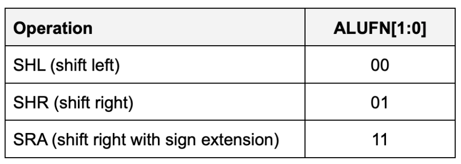
With this encoding, the control signal ALUFN0 controls whether we are performing a left shift or a right shift (SHR). ALUFN1 decides whether we apply the sign extension logic on right shift.
- For
SHLandSHR,0s are shifted into the vacated bit positions. - For
SRA(“shift right arithmetic”), the vacated bit positions are all filled withA31, the sign bit of the original data so that the result will be the same as arithmetically dividing the original data by the appropriate power of 2.
Detailed Shifter Unit Schematic
The simplest implementation is to build three separate shifters: one for shifting left, one for shifting right, and one for shifting right arithmetic.

Notice how a multi-bit shift can be accomplished by cascading shifts by various powers of 2.
- For example, a 13-bit shift can be implemented by a shift of 8, followed by a shift of 4, followed by a shift of 1.
- Each shifter unit is just a cascade of multiplexers each controlled by one bit of the shift count.
Afterwards, we can use a 4-way 32-bit multiplexer to select the appropriate answer as the unit’s output.
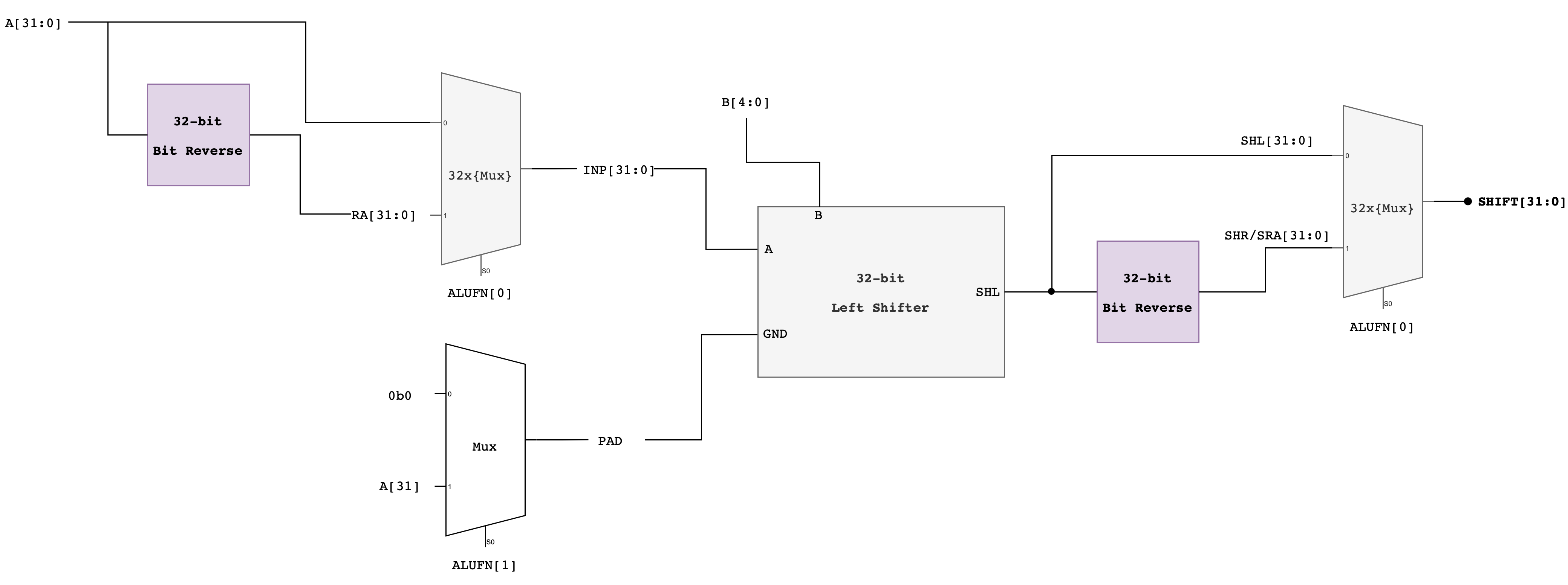
Alternative Approach: Compact Shifter
Another approach that adds latency but saves gates is to use the left shift logic for both left and right shifts, but for right shifts, reverse the bits of the
Ainput first on the way in and reverse the bits of the output on the way out.Here’s the schematic of this compact shifter.
Implementation Tips
You might want to use the MUX_2.luc module here to help your implementation:
module MUX_2 (
    input s0,
    input in[2], // note: you can put input as an array, or declare them separately, e.g: input d0, input d1
    // it will affect how you utilise this MUX
    output out
  ) {

  always {
    case (s0) {
      0: out = in[0];
      1: out = in[1];
      default:
        out = 0;
    }
  }
}
Then, you might want to utilise the following x_bit_left_shifter.luc unit, where x is an arbitrary value depending on SIZE parameter. You can supply a SHIFT parameter to this module:
module x_bit_left_shifter #(
    // parameter declaration, to be set during module instantiation
    // default value given is 8
    SHIFT = 8 : SHIFT > -1 & SHIFT < 32,
    SIZE = 32 : SIZE > 0
  )(
    input a[SIZE],
    input do_shift,
    input pad,
    output out[SIZE]
  ) {

  // module declarations
  // instantiate MUX_2 (32 of them)
  // other useful intermediary signals, e.g: shifted_bits[32]
  MUX2 shift_unit[SIZE];
  sig in_1shift_unit[SIZE]; // input s1 of each shift_unit MUX

  always {

    // assign value to shifted_bits[32] depending on the value of SHIFT
    // connect the selector of each MUX_2 with shift
    shift_unit.s0 = SIZEx{do_shift};
    in_1shift_unit = c{a[SIZE-1-SHIFT:0], SHIFTx{pad}};

    // use a repeat-loop to:
    // connect input[0] of each MUX_2 with a[i]
    // connect input[1] of each MUX_2 with the shifted_bits[i]
    repeat(i, SIZE){
       shift_unit.in[i] = c{in_1shift_unit[i], a[i]};
    }

    out = shift_unit.out;

  }
}
Then you can utilise it to create a left_shifter unit by instantiating 5 of the x_bit_left_shifter:
module left_shifter (
    input a[32],
    input b[5],
    input pad, // 0 or 1 to pad the empty spaces
    output shl[32]
  ) {

  // instantiate 5 units of left shifter with different values
  x_bit_left_shifter shifter16(#SHIFT(16));
  x_bit_left_shifter shifter8(#SHIFT(8));
  x_bit_left_shifter shifter4(#SHIFT(4));
  x_bit_left_shifter shifter2(#SHIFT(2));
  x_bit_left_shifter shifter1(#SHIFT(1));

  always {

    // connect the padding
    shifter16.pad = pad;
    shifter8.pad = pad;
    shifter4.pad = pad;
    shifter2.pad = pad;
    shifter1.pad = pad;

    // enable or disable each shifter using each bit of b
    shifter16.a = a;
    shifter16.do_shift = b[4];

    shifter8.a = shifter16.out;
    shifter8.do_shift = b[3];

    shifter4.a = shifter8.out;
    shifter4.do_shift = b[2];

    shifter2.a = shifter4.out;
    shifter2.do_shift = b[1];

    shifter1.a = shifter2.out;
    shifter1.do_shift = b[0];

    // set output as the output of the smallests shifter
    shl = shifter1.out;
  }
}
Refer to the above two modules to create a right shifter set, or use the alternative approach above.
Instance Parameters
If you want to create instances of N modules with the same parameter, you can use this format:
#PARAM_NAME(VALUE) {
    module_type my_module[N]
}
In the above example, all N instances of module_type will have their parameter, PARAM_NAME set to VALUE (must be a constant).
If you want to assign different parameter to each instance, then you need to create an array of N by M, where M is the number of bits required to set VALUE for each instance. For example, we can instantiate 10 my_module with parameter of 8 bits each as follows:
module_type my_module[10](#PARAM_NAME({8d0, 8d1, 8d2, 8d3, 8d4, 8d5, 8d6, 8d7}))
This does not apply to the dff. The clk and rst inputs are always 1 bit and the INIT parameter always applies to the FULL dff. If you do dff storage[32](#INIT(32hABCDFFFF)) then it will store 32-bit value 0xABCDFFFF in these 32 bits dff, where each dff holds 1 bit.
Test
Testbench
testbench test_shifter {
    shifter shifter
    const TEST_CASES_SHIFT = $reverse({
            // 1. SHL: simple left shift
            c{32d1,           32d1,           2b00, 32d2},
            // 2. SHL: overflow bits dropped
            c{32h80000000,    32d1,           2b00, 32h00000000},
            // 3. SHL: shift amount masked (33 -> 1)
            c{32d1,           32d33,          2b00, 32d2},
            // 4. SHR: simple logical right shift
            c{32d8,           32d2,           2b01, 32d2},
            // 5. SHR: negative value zero-filled
            c{32h80000000,    32d1,           2b01, 32h40000000},
            // 6. SHR: shift amount masked (32 -> 0, no shift)
            c{32h80000000,    32d32,          2b01, 32h80000000},
            // 7. SRA: arithmetic right shift with sign extend
            c{32h80000000,    32d1,           2b11, 32hC0000000},
            // 8. SRA: large shift yields all ones
            c{32h80000000,    32d31,          2b11, 32hFFFFFFFF}
        })

    test shifterTest {
        repeat (i, 8){
            shifter.a  = TEST_CASES_SHIFT[i][97:66]
            shifter.b  = TEST_CASES_SHIFT[i][65:34]
            shifter.alufn = c{4b1000,TEST_CASES_SHIFT[i][33:32]}
            $tick()
            $assert(shifter.shift == TEST_CASES_SHIFT[i][31:0])
            $print("PASS test case: %d", i+1)
        }
    }
}
Simulator and Hardware Test
As usual, do not forget to test it manually on the simulator as well as the hardware once your unit passes the testbench.
Test the shifter.luc module by making appropriate connections in alu.luc before proceeding. Be mindful when testing this unit, it should be as comprehensive as the tests you’ve done for the other 3 units above.
  // alu.luc body
  alu_output = shifter.shift
Task 5: Multiplier
The multiplier unit performs a multiplication between 32-bit inputs A and B each, and produce a 32-bit output.
Multiplying two 32-bit numbers produces a 64-bit product. However, the result we’re looking for is just the low-order 32-bits of the 64-bit product since our hardware is built to only supports 32-bit outputs.
4-bit Multiplication Logic
It’s hard to imagine a 32-bit multiplier straight up, so let’s scale down to a 4-bit version.
Suppose we want to multiply two 4-bit binary numbers: A = 1011 (which is 11 in decimal) and B = 1101 (which is 13 in decimal).
The multiplication process involves the following steps:
- Write Down the Multiplicands: Write A and B such that each bit of B is aligned under each bit of A.
- Multiply Each Bit of B by A: Multiply each bit of B with the entire number A, shifting the result to the left for each subsequent bit. In binary multiplication, this means we either take A (if the bit in B is 1) or take 0 (if the bit in B is 0).
- Add the Partial Products: Add all the partial products together to get the final result.
    1011   (A = 11 in decimal)
  x 1101   (B = 13 in decimal)
  ------
    1011   (This is A * 1; the rightmost bit in B is 1)
   0000    (This is A * 0; shift left by 1 because we're on the second bit from the right in B)
  1011     (This is A * 1; shift left by 2)
 1011       (This is A * 1; shift left by 3)
------
10001111   (Sum of the above partial products)
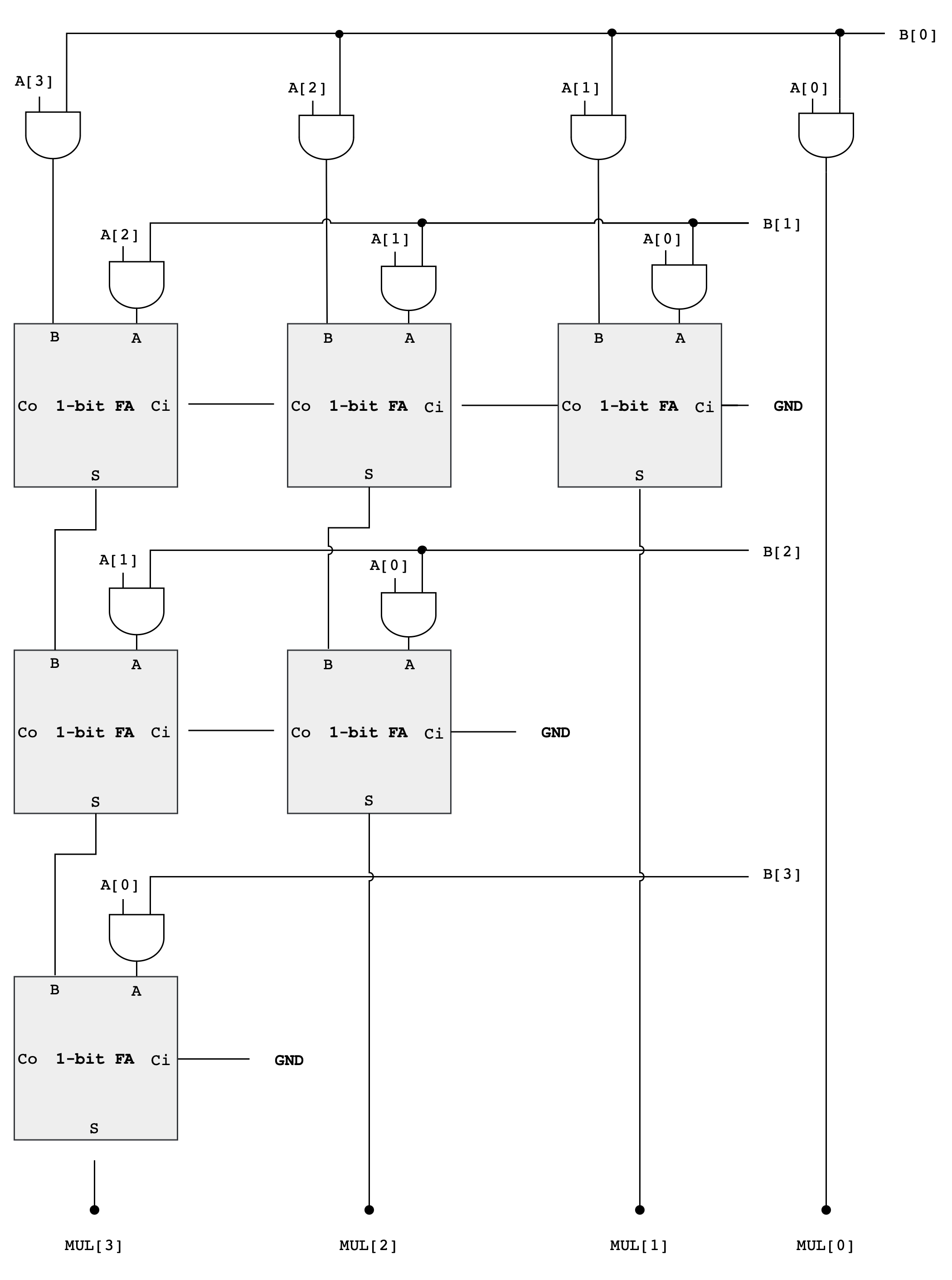
Here is a detailed bit-level description of how a 4-bit by 4-bit unsigned multiplication works. This diagram assumes we only want the low-order 4 bits of the 8-bit product.
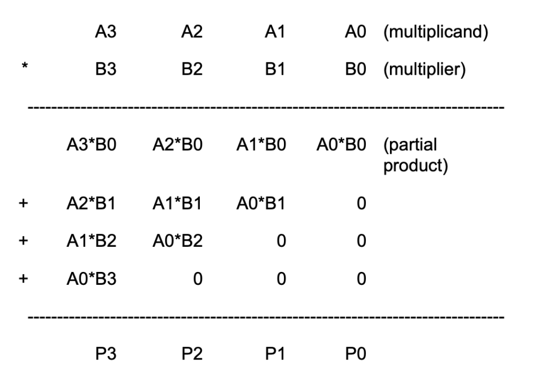
This diagram can be extended in a straightforward way to 32-bit by 32-bit multiplication. Remember that since our machine is only 32-bit, that means we only can store the low-order 32-bits of the result, we don’t need to include the circuitry that generates the rest of the 64-bit product.
4-bit Multiplier Schematic
As you can see from the diagram above, forming the partial products is easy. Multiplication of two bits can be implemented using an AND gate. The hard and tedious part is adding up all the partial products (there will be 32 partial products in your circuit).
- One can use FA units hooked up in a ripple-carry configuration to add each partial product to the accumulated sum of the previous partial products (see the diagram below)
- The circuit closely follows the diagram above but omits an FA module if two of its inputs are
0
Multiplier Analysis
The circuit above works with both unsigned operands and signed two’s complement operands.
Why do we ignore the MSB of the operands?
This may seem strange, don’t we have to worry about the most significant bit (MSB) of the operands? With unsigned operands the MSB has a weight of \(2^{MSB}\) (assuming the bits are numbered 0 to MSB) but with signed operands the MSB has a weight of \(-2^{MSB}\).
Doesn’t our circuitry need to take that into account?
Turns out it does, but when we are only saving the lower half of the product, the differences don’t appear. The multiplicand (A in the figure above) can be either unsigned or two’s complement (signed), and the FA circuits will perform correctly in either case.
When the multiplier (B in the figure above) is signed, we should subtract the final partial product instead of adding it.
- But subtraction is the same as adding the negative, and the negative of a two’s complement number can be computed by taking its complement and adding 1.
- When we work this through we see that the low-order bit of the partial product is the same whether positive or negated.
The low-order bit is ALL that we need when saving only the lower half of the product.
If we were building a multiplier that computed the full product, we’d see many differences between a multiplier that handles unsigned operands and one that handles two’s complement (signed) operands, but these differences only affect how the high half of the product is computed.
Example: 4-bit Signed Multiplication
Let’s use a 4-bit example to illustrate why the lower half of the product is the same whether we are dealing with signed or unsigned numbers, especially in the context of two’s complement arithmetic.
Suppose we have A = 0110 (6 in decimal) multiplied by B = 1101 (-3 in decimal, two’s complement).
As Unsigned Numbers, they are:
A = 0110(6 in decimal)B = 1101(13 in decimal, treated as unsigned)
The multiplication (ignoring overflow) of these two numbers is:
   0110   (A = 6)
 x 1101   (B = 13, as unsigned)
 ------
   0110   (A * 1)
  0000    (A * 0, shift left by 1)
 0110     (A * 1, shift left by 2)
0110      (A * 1, shift left by 3)
------
1001110   (78 in decimal, unsigned)
However, the multiplication as signed numbers works differently because the last partial product should be negated:
    0110   (A = 6)
  x 1101   (B = -3, as signed)
  ------
    0110   (A * 1)
   0000    (A * 0, shift left by 1)
  0110     (A * 1, shift left by 2)
 1010000   (A * 1, shift left by 3, we get 0110000 but it should be negated, resulting in 1010000)
------
 1101110 (-18 in decimal, signed)
The negation of
0110000is1010000(flip the bits, then add 1).
In both cases, the lower half of the product (1110) is the same. This is because the difference caused by the negative MSB in the two’s complement representation affects only the higher-order bits, which are outside the lower half of the product.
When multiplying two numbers where the sign of one is significant (like in two’s complement), the alterations to the upper bits due to the sign are not reflected in the lower bits. This is why, in certain computational scenarios where only the lower half of the product is of interest, the circuitry can be simplified as it doesn’t need to differentiate between signed and unsigned numbers.
Design Note
Combinational multipliers implemented as described above are pretty slow! There are many design tricks we can use to speed things up – see the appendix on “Computer Arithmetic” in any of the editions of Computer Architecture: A Quantitative Approach by John Hennessy and David Patterson (Morgan Kauffmann publishers).
Test
Testbench
Your computer might lag a little bit while running the testbench due to the complexity of the multiplier hardware.
testbench test_multiplier {
    multiplier multiplier
    const TEST_CASES_MUL = $reverse({
            // 1. small positive multiply
            c{32d3,           32d4,           32d12},
            // 2. multiply by zero
            c{32d12345,       32d0,           32d0},
            // 3. negative times positive
            c{-32d7,          32d6,          -32d42},
            // 4. negative times negative
            c{-32d8,         -32d5,           32d40},
            // 5. large values with truncation (lower 32 bits kept)
            c{32hFFFFFFFF,    32d2,           32hFFFFFFFE},
            // 6. sign bit interaction
            c{32h80000000,    32d2,           32h00000000},
            // 7. power-of-two scaling
            c{32d1024,        32d1024,        32d1048576},
            // 8. overflow wraps around
            c{32h7FFFFFFF,    32d2,           32hFFFFFFFE}
        })

    test myTest {
        repeat (i, 8){
            multiplier.a  = TEST_CASES_MUL[i][95:64]
            multiplier.b  = TEST_CASES_MUL[i][63:32]
            $tick()
            $assert(multiplier.mul == TEST_CASES_MUL[i][31:0])
            $print("PASS test case: %d", i+1)
        }
    }
}
Simulator and Hardware Test
As usual, do not forget to test it manually on the simulator as well as the hardware once your unit passes the testbench.
Connect the output of your multiplier to the output of your alu for now:
// alu.luc body
  alu.out = multiplier.mul;
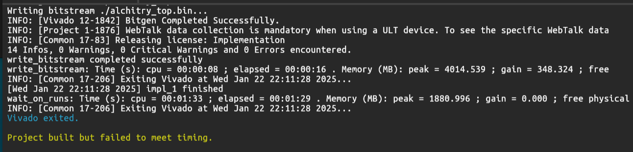
Failed Timing Warning (Hardware)
This 32-bit combinational multiplier, as part of the ALU, may fail to meet the timing specifications for a 100 MHz clock in a sequential device. However this should still produce a working binary and does not affect other parts of your ALU. It might even give the right output for the multiplier (small bit multiplications).
Basically, if your project fails timing, that means your design logic is too slow to keep up with the 100 MHz clock (i.e., 10 ns per cycle). Even if Vivado compiles it, the actual hardware may behave unpredictably. You should lower the clock frequency in the constraint file (e.g., set to 10 MHz) so Vivado checks for more relaxed timing.
To address this, you can modify the constraint file to let Vivado analyze with a slower clock, e.g 10MHz.
Create a new constraint file (you can name it anything) and paste the content of alchitry.acf to it, and modify the clock signal. Don’t forget to delete the default alchitry.acf.
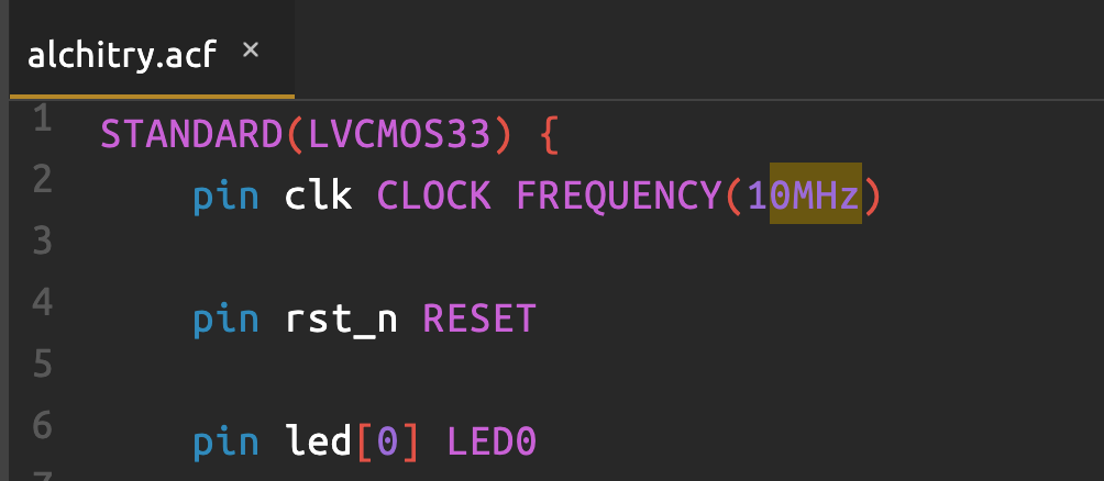
But remember: the onboard clock is still 100 MHz. You must manually slow your logic (e.g., FSM or output updates in ALU Manual Tester) to match this by adding delay logic (like a clock divider). For example: delay each FSM state by 10 times using a counter, so your effective FSM cycle is 1 per microsecond instead of 1 per 10 ns. Consult this handout for details.
As part of your 2D project: Optimisation part, you can consider using other multiplier designs that can pass the original 100MHz clk.
Task 6: Assembling the ALU
You are free to implement each module in whichever way you deem fit, or even come up with a new schematic as long as you don’t use Lucid’s math operators and compare operators to implement any of these 13 functionalities. You can however use them for indexing purposes or conditional loops.
Finally, open alu.luc and assemble the outputs of the finished adder, multiplier, compare, boolean and shift units to produce 32-bit alu output alu_output[31:0] based on the input ALUFN signal. The simplest approach is to use a 4-way 32-bit multiplexer as shown in the schematic below:
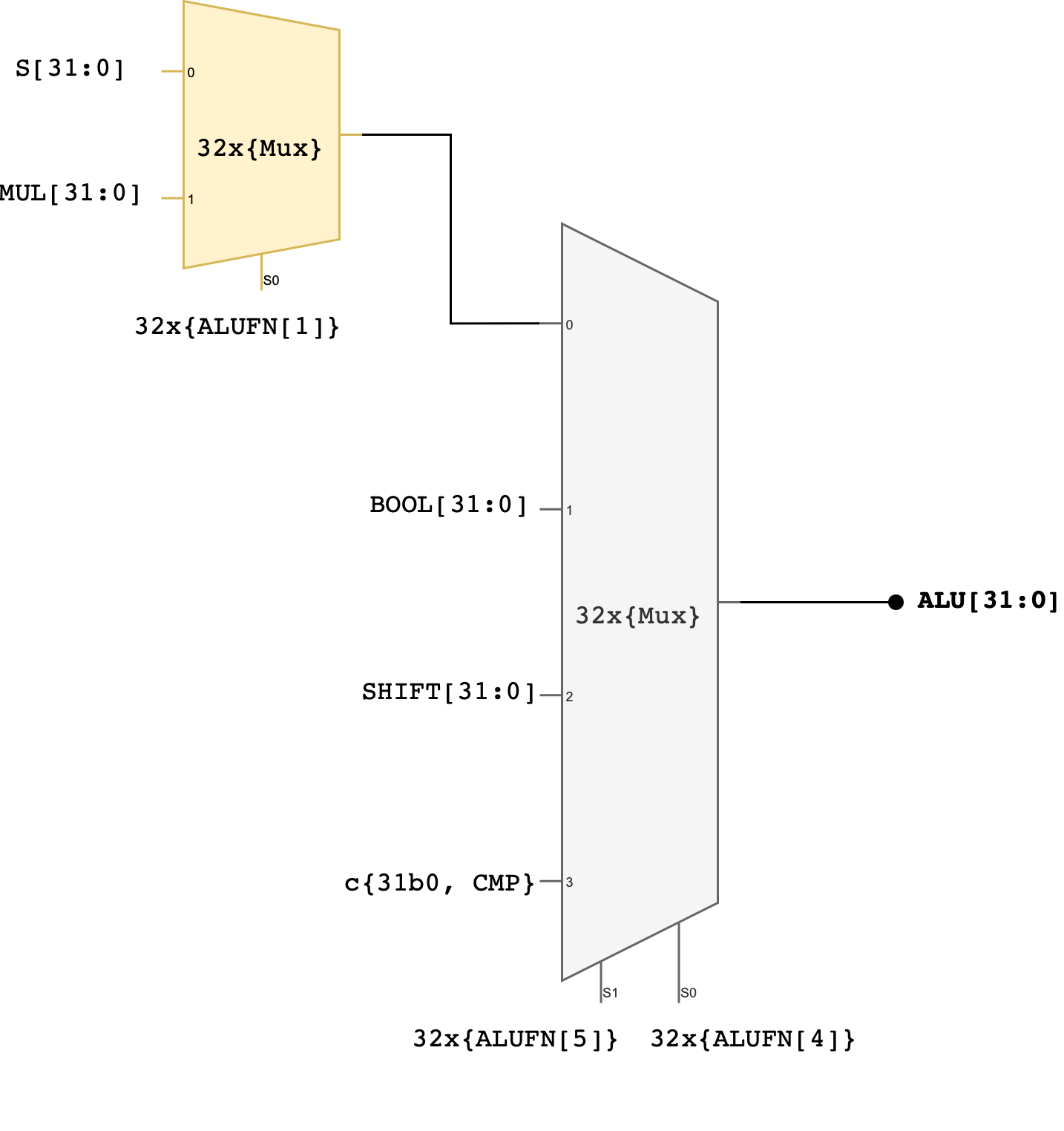
You can use MUX2to4, or use the case statement, or use plain if-else statements.
Two control signals (ALUFN[5:4]) that we have never used before in the individual module have now been utilised to select which unit will supply the value for the ALU output. The encodings for ALUFN[5:0] should follow this table that you’ve seen in the beginning of this handout:
Note that the Z, V, and N signals from the adder/subtractor unit are included in the terminal list for the alu subcircuit (they’re counted as ALU’s output). Please connect these terminals properly in your alu.luc file.
ALU Tester
Ensure that you test your ALU comprehensively because you will be using it for your 1D project. You wouldn’t want to discover some bugs down the road as your project grows larger. Here’s some suggestions (you’re not limited to these, think of more!):
- ADD (0x00)
- Zero Addition:
A + 0and0 + Ato ensure correct handling of zero. - Positive Numbers: Add two positive numbers.
- Boundary Values: Add the maximum positive number to itself and ensure correct handling of overflow.
- Check for overflow by adding two very big positive numbers
- Zero Addition:
- SUB (0x01)
- Zero Subtraction:
A - 0and0 - Ato test for correct subtraction with zero. - Underflow: Subtract a larger number from a smaller one to test for underflow.
- Boundary Values: Subtract the maximum positive number from zero and check for correct negative result in two’s complement.
- Zero Subtraction:
- MUL (0x02)
- Zero Multiplication: Multiply by 0 to ensure the result is 0.
- Multiplication by One:
A * 1should yieldA. - Positive Numbers: Multiply two positive numbers and check for correct results.
- Overflow (not compulsory, only if it’s relevant to your project): Multiply two numbers that will cause overflow and ensure it is handled correctly.
- AND (0x18)
- All Zeros and Ones:
A AND 0should be 0,A AND 0xFFFF(assuming 16-bit operands) should beA. - Identity Check:
A AND Ashould giveA. - Complement Check:
A AND NOT Ashould give 0.
- All Zeros and Ones:
- OR (0x1E)
- All Zeros and Ones:
A OR 0should beA,A OR 0xFFFFshould be 0xFFFF. - Identity Check:
A OR Ashould giveA.
- All Zeros and Ones:
- XOR (0x16)
- Identity Check:
A XOR 0should giveA,A XOR Ashould give 0. - Complement Check:
A XOR NOT Ashould give 0xFFFF.
- Identity Check:
- “A” (LDR) (0x1A)
- Load Function: Ensure that inputting
AgivesA, and does not modify it.
- Load Function: Ensure that inputting
- SHL (0x20)
- Zero Shift: Shifting
Aby 0 should yieldA. - Maximum Shift: Shifting a number by the width of the data bus minus one.
- Boundary Cases: Shift a number with a 1 in the MSB and ensure it is handled correctly.
- Zero Shift: Shifting
- SHR (0x21)
- Zero Shift: Shifting
Aby 0 should yieldA. - Maximum Shift: Shifting a number by the width of the data bus minus one.
- Logical Shift: Ensure that the vacated bits are filled with 0.
- Zero Shift: Shifting
- SRA (0x23)
- Arithmetic Right Shift: Ensure the sign bit is replicated to preserve the sign of the number.
- CMPEQ (0x33)
- Equality: Test with equal values to ensure the result is true.
- Inequality: Test with different values to ensure the result is false.
- CMPLT (0x35)
- Less Than: Test where
Ais less thanB. - Greater Than or Equal: Test where
Ais greater than or equal toBto ensure the result is false.
- Less Than: Test where
- CMPLE (0x37)
- Less Than or Equal: Test where
Ais less than or equal toB. - Greater Than: Test where
Ais greater thanBto ensure the result is false.
- Less Than or Equal: Test where
1D Project Checkoff 1
For your 1D Checkoff 1: ALU, you are required to make both manual and automated ALU tester (like the automated Adder tester in your previous lab). See the 1D handout for more information.
Testbench
Create your own testbench with various test cases. Here’s one to get you started:
testbench test_alu {
    alu alu
    const TEST_VALUES_ALU = $reverse(
        {
            c{32d0,          32d0,          6h00, c{32d0,          1b1,1b0,1b0}}, // 00 ADD 0+0
            c{32h7FFFFFFF,   32d1,          6h00, c{32h80000000,   1b0,1b1,1b1}}, // 01 ADD pos overflow

            c{32d7,          32d5,          6h01, c{32d2,          1b0,1b0,1b0}}, // 02 SUB 7-5
            c{32h80000000,   32d1,          6h01, c{32h7FFFFFFF,   1b0,1b1,1b0}}, // 03 SUB neg overflow

            c{32d3,          32d4,          6h02, c{32d12,         1b0,1b0,1b0}}, // 04 MUL 3*4
            c{32h80000000,   32d2,          6h02, c{32d0,          1b0,1b0,1b1}}, // 05 MUL 80000000*2

            c{32hF0F0F0F0,   32h0F0F0F0F,   6h18, c{32h00000000,   1b0,1b0,1b1}}, // 06 AND mask clears to zero
            c{32hF0F0F0F0,   32h0F0F0F0F,   6h1E, c{32hFFFFFFFF,   1b0,1b0,1b1}}, // 07 OR fills all bits
            c{32hAAAA5555,   32hFFFF0000,   6h16, c{32h55555555,   1b0,1b0,1b1}}, // 08 XOR pattern

            c{32d5,          32d7,          6h1A, c{32d5,          1b0,1b0,1b0}}, // 09 PASSA 5,7

            c{32d1,          32d3,          6h20, c{32d8,          1b0,1b0,1b0}}, // 10 SHL 1<<3
            c{32d16,         32d1,          6h21, c{32d8,          1b0,1b0,1b0}}, // 11 SHR 16>>1
            c{32h80000000,   32d1,          6h23, c{32hC0000000,   1b0,1b1,1b0}}, // 12 SRA 80000000>>1

            c{32d5,          32d5,          6h33, c{32d1,          1b1,1b0,1b0}}, // 13 CMPEQ 5==5
            c{32d3,          32d7,          6h35, c{32d1,          1b0,1b0,1b1}}, // 14 CMPLT 3<7 true
            c{32d5,          32d5,          6h37, c{32d1,          1b1,1b0,1b0}}  // 15 CMPLE 5<=5
        }
    )

    test aluTest {
         repeat(i, 16){
            alu.a = TEST_VALUES_ALU[i][104:73]
            alu.b = TEST_VALUES_ALU[i][72:41]
            alu.alufn = TEST_VALUES_ALU[i][40:35]
            $tick()
            $assert(alu.out == TEST_VALUES_ALU[i][34:3])
            $assert(alu.z == TEST_VALUES_ALU[i][2])
            $assert(alu.v == TEST_VALUES_ALU[i][1])
            $assert(alu.n == TEST_VALUES_ALU[i][0])
            $print("PASS test case: %d", i+1)
        }
    }
}
Manual Test (Simulator)
Ensure your ALU works as expected in the simulator using manual tester.
- We must be able to key in 32-bit A, 32-bit B, and 6-bit ALUFN. Create an FSM for this.
- Then we must be able to observe all 32-bit of results, viewing 16-bit at a time.
In this recording, we tested a SUB negative overflow, bitwise XOR, and SRA:
- SUB negative overflow:
A = 32h8000000, B = 32h1 - XOR:
A = 32hF, B = 32hF0 - SRA:
A = 3280000080, B = 32h3

You are free to use a different interface if you wish.
Automated Test (Simulator)
Ensure your ALU works as expected in the simulator using automated tester.
- It must be able to loop through comprehensive test cases automatically
- It has a forced-error switch that will STOP the automated tester immediately, and you can restart it
- It should be able to report the index/any indication of the test case id at human-readable rate
- You may use the
io_buttonsto display the alu/test output, 8-16 bits at a time (optional) - You should be able to simulate error cases like you did in the previous lab when you build the automated adder tester
- Use a dip switch to induce an error, like bit-flipping the ALU output before feeding it to the automated tester
- Your tester should stop immediately or report the error index id later
You can reuse the automated fsm and datapath tester you built in the previous lab to make the automated ALU tester. Simply change the interface (to support 32 bits) and create alu test cases instead. Here we use io_dip[2][6] to switch between manual mode and automated mode.

Simulation tips
Your simulator will lag terribly with such a large scale multiplier module. You may TEMPORARILY disable your multiplier unit and replace it with
a*bso that your simulator that tests the ALU functionalities runs faster. Of course this should be done only after extensively testing your multiplier module as a standalone so you already know that your design works!
Manual Test (Hardware)
Once it works in simulator, do not forget to test in hardware as well. It should work the same as the simulator. Here’s a simple recording testing the same functionalities as above:
Automated Test (Hardware)
Ensure your automated tester works as intended on hardware too:
Operator Precedence
HDLs like Verilog has a long precedence table covering unary, arithmetic, shift, relational, equality, bitwise, reduction, logical, and conditional operators. Since Lucid is transpiled to Verilog, you might need to be aware of this. You do not need to memorize it, but you do need a habit that protects you from the cases where the default grouping is not what your eyes tell you it should be.
Reduction versus bitwise
// Intent: "all low 3 bits of wr_ptr are 1, AND the edge pulse is high"
sig bad  =  &wr_ptr[2:0]  &  edge_pulse;   // parses as &(wr_ptr[2:0] & edge_pulse)
sig good = (&wr_ptr[2:0]) && edge_pulse;   // parses as intended
The unary reduction & has lower precedence than the binary bitwise &, so the bad line does the bitwise AND first and the reduction second. The 1-bit edge_pulse is zero-extended against the 3-bit slice, the bitwise AND collapses two of the three bits to zero, and the outer reduction can never be true. The signal never asserts and nothing in the syntax warns you.
Bitwise versus equality
sig bad  = a & b == 4'd0;     // parses as a & (b == 4'd0)
sig good = (a & b) == 1'b0;   // probably what you meant
Equality has higher precedence that bitwise AND, so the bad line compares b to zero first and then ANDs that 1-bit result with a. If you wanted “the AND of a and b equals zero”, the parser disagrees with you.
Shift versus addition
sig [7:0] bad  = x + y << 1;     // parses as (x + y) << 1
sig [7:0] good = x + (y << 1);   // y doubled, then added to x
Addition has higher precedence than shift, so x + y << 1 adds first and shifts the sum. People who think of shifts as “just multiplication” expect them to follow the precedence of *, but they do not.
Conditional versus arithmetic
sig [7:0] bad  = sel ? a : b + c;     // parses as sel ? a : (b + c)
sig [7:0] good = (sel ? a : b) + c;   // pick a or b, then add c
The conditional operator ?: has very low precedence, lower than almost everything else. The + c on the right gets absorbed into the false branch instead of being applied to the result of the select.
Logical AND versus logical OR
sig bad  =  |status && ready || enable;
sig good = ((|status) && ready) || enable;
This one technically parses the way most people want, because && binds tighter than ||. But a reader cannot see that without consulting the proper documentation. Therefore, the parenthesized version takes one extra second to type and removes any doubt.
A case that is actually fine
sig y[15:0] = -a * b; // parses as (-a) * b
Unary operators has higher precedence than binary ones, so this does what you expect. Not every mixed expression is a trap. The point of the rule below is not that Verilog precedence is always wrong, it is that you should not have to stop and check.
Whenever you mix operators of different kinds in one expression (reduction with bitwise, bitwise with logical, comparison with arithmetic, shift with anything, or a conditional with anything else) wrap each sub-expression in parentheses. If an expression is short enough that the precedence is obvious, like a single comparison or a single arithmetic operation, parentheses are optional. Once two different operator families appear in the same line, treat parentheses as mandatory. The cost of an extra pair of parentheses is one keystroke. The cost of finding a misparsed condition in a waveform is an hour of staring at signals that look right but are not.
Summary
Congratulations 🎉🎉! You have successfully built a 32-bit ALU in this lab and familiarse yourself with programming FPGA with Lucid. You will be required to utilise it in Lab 6 (Beta CPU), so please keep a copy of your answer.
For your 1D project, you need to demonstrate a working ALU in your Alchitry Au FPGA hardware (not simulator!). Both your manual and automated simulator must work on hardware. Read the FPGA tutorials linked in our course handout for further information, and don’t forget to polish your knowledge on Sequential Logic before proceeding.
Carefully consult Checkoff 1: ALU schedule, requirements and rubrics given in the course handout. Do not miss your checkoff slot.
Checkoff
Checkoff Schedule
Consult course handout for 1D Project Checkoff 1 schedule. We will also do Lab 5 checkoff at the same time
Details
As a recap, to get full marks for this lab and 1D Project Checkoff 1: ALU you must complete the following:
- Lab 5 implementation checkoff (2%)
- (0.5%) Your ALU must pass a comprehensive automated testbench (you may use the provided testbenches or your own, but they must cover all 13 ALU operations).
- (0.5%) You must have a working manual and automated ALU tester in the SIMULATOR.
- (1%) Instructors/TAs will ask you two questions (same protocol as lab 2) about any code you write in the project
- Lab 5 questionnaire (2%)
- Complete the Lab 5 questionnaire on eDimension.
- 1D Project Checkoff 1: ALU (3%)
- The same ALU must have a working manual and automated tester on the FPGA HARDWARE.
- Don’t forget the error case requirement, read the 1D checkoff 1 handout and rubrics for more details
Unless otherwise specified, all ALU checkoff marks (2% lab implementation + 3% 1D ALU) are awarded per 1D project group. The eDimension questionnaire is graded per individual.
Give the 1D handout a read before Checkoffs to ensure that you don’t miss any information or requirements.
For 1D Checkoff 1: ALU, you’re ALSO required to create additional functionalities. You are allowed to use Lucid math and comparison operator for this NEW functionality. For example, if your new operation involves ROTATE_SHIFT between A and B, you’re allowed to implement it as follows:
module rotate_shift_right (
    input a[32],
    input b[5],
    output shift[32]
  ) {

  always {
    shift = (a >> b) | (a << (32 - b))
  }
}

module rotate_shift_left (
    input a[32],
    input b[5],
    output shift[32]
  ) {

  always {
    shift = (a << b) | (a >> (32 - b))
  }
}
Only the original 13 functionalities must be implemented using logic gates as per the circuitry given in this lab handout.
Avoid Division by Non-Powers of 2
Do not use expressions like a / b where b is not a power of 2.
Division in hardware is complex: it requires a divider circuit, which is large, slow, and significantly more complicated than an adder or shifter. Most hardware division uses restoring or non-restoring algorithms, or iterative subtraction, which take multiple clock cycles. This introduces sequential logic into your ALU, instead of keeping it purely combinational. As a result, it can mess up your timing, increase your critical path delay, and make synthesis and debugging harder.
If you need to divide by a power of 2, use right shifts instead.
When you’re done with the implementation of your ALU, head to eDimension to complete this lab quiz.