 50.002 CS
- Beta Instruction Replacements (Intermediate)
- PCSEL Fault Detection (Intermediate)
- Quality Control (Intermediate)
- A Confused Beta CPU (Hard)
50.002 Computation Structures
Information Systems Technology and Design
Singapore University of Technology and Design
Beta CPU Diagnostics
Each topic’s questions are grouped into three categories: basic, intermediate, and challenging. You are recommended to do all basic problem set before advancing further.
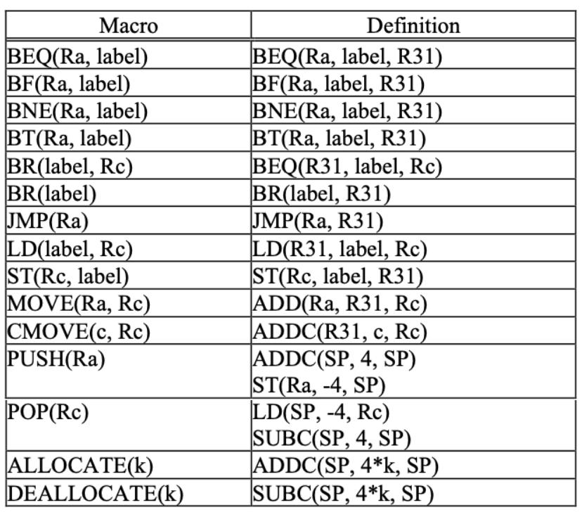
Before you proceed, we suggest you explore the bsim and read the beta documentation given in the course handout, especially this section called Convenience Macros that makes it easier to express certain common operations.
Beta Instruction Replacements (Intermediate)
For each of the statements below, indicate whether they’re True or False and provide your reasoning.
- Statement 1: In the Beta, every
ADDCinstruction can always be replaced by aSUBCinstruction that puts precisely the same value in the destination register. For example,ADDC(R0,1,R0)is equal toSUBC(R0,-1,R0)(think about all constants). - Statement 2: In a Beta program, you can use
BEQ(R31, label, R31)as a substitute forJMP(Ra)whereRastores the address oflabel, no matter wherelabelis. - Statement 3: We can never perform
LDandSTto any two independent addresses in a single cycle (even if the memory unit supports it) by just modifying the control unit of the Beta. In other words, we need to modify the datapath of the Beta in order to do this.
Statement 1 is False. We can have ADDC(R0, -32768, R0) but we cant have SUBC(R0, 32768, R0) as the most positive number that a signed 16-bit can represent is 32767.
Statement 2 is False. Ra contains 32-bit of data, so we can set PC to be pointing to any address in the memory (4GB of address space) with JMP(Ra). However, BEQ only covers 32768 times 4 (above PC+4) + 32768 times 4 (*below and inclusive of PC+4*) bytes of address space.
Statement 3 is True. The output of the ALU supplies a single address for both load and store to the memory unit.
PCSEL Fault Detection (Intermediate)
This time round, consider a Beta machine with a faulty control unit, where its PCSEL signal is always 0, meaning that the input to the PC register is always PC+4 regardless of the instruction.
As always, we can detect this particular fault by running a simple test program written in Beta assembly language. State which of the following programs can detect this particular fault, meaning that if it was to be run on a faulty Beta machine, we will get different results (contents) on the registers in the regfiles, PC, or Memory Unit, and provide your reasoning.
Assume that all register values were 0 at the beginning of each program execution.
Program 1: (executed for two CLK cycles)
.= 0
BEQ(R0, .+4, R31)
ADDC(R0, 1, R0)
Program 2: (executed for three CLK cycles)
.=0
CMPEQ(R0, R0, R0)
BNE(R0, .-4, R31)
ADDC(R0, 1, R0)
Program 3: (executed for four CLK cycles)
.=0
LD(R0, 0, R0)
MULC(R0, 1, R0)
BNE(R0, .+4, R31)
CMPEQ(R0, R31, R2)
Program 4: (executed for two CLK cycles)
.=0
ST(R0, x, R31)
x: LONG(12)
Program 5: (executed for two CLK cycles)
.=0
JMP(R1)
ADDC(R0, 1, R1)
Program 6: (executed for two CLK cycles)
.=0
LDR(.+8, R0)
ADDC(R0, 1, R1)
x : LONG(3)
Program 2, 4, and 5 can successfully detect this faulty. All of them forces the control unit to produce non-zero PCSEL. For example, Program 4 results in illop when the Beta attempts to execute LONG(12) because it isn't an instruction. Therefore PCSEL=3 if the control unit works properly and that the content of PC will be ILLOP (wherever the address of illegal operation handler is) instead of address 0xC.
Quality Control (Intermediate)
One Beta manufacturer is having quality-control problems with their design. In particular, they’ve had reliability issues with various device connections that are circled in the diagram below.

Your job is to write some test programs to help determine if a machine is fault-free. Assume that when a device connection is faulty, the indicated bus or signal is always producing 0 instead of the expected value.
For each of the circled connections, write an instruction sequence that when executed for a specified number of cycles will leave the following result in R0:
1inR0if the connection was working.- Other values in
R0if the connection was faulty.
You can assume that all registers are reliably set to 0 before each sequence is executed. There’s many possible answers, they aren’t unique.
Give your instruction sequence for each of the six indicated faults and briefly explain how each sequence detects the fault and produces something besides 1 in R0 when the fault is present:
- Fault A: Input 1 of
PCSELMUX has a value of0instead ofPC+4+4*SEXT(C). - Fault B:
RA2SELmultiplexer control signal is0instead of as per intended current instructionOPCODE. - Fault C:
Zinput to control logic is always0instead of the correct value depending onRD1. - Fault D:
BSELmultiplexer control signal0instead of as per intended current instructionOPCODE. - Fault E:
WRmemory control signal is0instead of as per intended current instructionOPCODE. - Fault F: Input 0 of
WDSELMUX has a value of0instead ofPC+4.
Fault A: Input 1 of PCSEL MUX has a value of 0 instead of PC+4+4*SEXT(C).
| starts at address 0
. = 0
BEQ(R0,.+4,R31) | 0x0
ADDC(R0,1,R0) | 0x4
- If fault A is not present,
R0contains1after the second cycle, since the second instruction is fetched from location0x4. - If fault A is present, the second instruction is fetched from location
0(instead of4, since the input1to thePCSELMUX is0), so the value ofR0stays0.
.+4 means “memory location of current instruction + 4”, which is 0+4 here.
Fault B: RA2SEL multiplexer control signal is 0 instead of as per intended current instruction OPCODE.
| starts at address 0
. = 0
ADDC(R1,1,R1)
ST(R1,0,R0)
LD(R0,0,R0)
- If fault B is not present, the
STinstruction writes the value1into location0, which is thenLD-ed (loaded) intoR0. - If fault B is present, the
STinstruction writes the contents ofR0instead (ie, the value0), so now theLDinstruction puts0intoR0.
Fault C: Z input to control logic is always 0 instead of the correct value depending on RD1.
| starts at address 0
. = 0
BEQ(R0,.+8,R31)
ADDC(R0,0,R0)
ADDC(R0,1,R0)
- If fault C is not present,
R0is incremented to1since the branch to memory location8is taken. - If fault C is present, the
BEQinstruction never branches, executing the instruction at location4, which leaves the contents ofR0unchanged (i.e., it's still0).
Fault D: BSEL multiplexer control signal 0 instead of as per intended current instruction OPCODE.
| starts at address 0
. = 0
ADDC(R0,1,R0)
- If fault D is not present,
R0is increment to1. - If fault D is present, the high-order 5-bits of the literal field (i.e., where
Rbis encoded) is used as a register address, and the contents of that register is added toR0. Since the literal is1, the second register isR0(containing0), so the value written intoR0is0.
Fault E: WR memory control signal is 0 instead of as per intended current instruction OPCODE.
| starts at address 0
. = 0
ADDC(R1,1,R1)
ST(R1,X,R31)
LD(R31,X,R0)
. = 0x100
X: LONG(0)
- If fault E is not present, the instruction writes the value
1intoMem[X], which is thenLD-ed (loaded) intoR0. - If fault E is present, the
STinstruction has no effect, so now theLDinstruction loads the original value of locationXintoR0.
Fault F: Input 0 of WDSEL MUX has a value of 0 instead of PC+4.
| starts at address 0
. = 0
BEQ(R0,.+4,R1)
SUBC(R1,3,R0)
- If fault F is not present, the
BEQinstruction loads4intoR1and theSUBCloads1intoR0. - If fault F is present, the
BEQinstruction loads0intoR1and theSUBCloads -3 intoR0.
A Confused Beta CPU (Hard)
When Alice was walking back to her hostel this morning, she dropped her Beta CPU and it hit the ground pretty hard. She suspected that these components do not work properly anymore:
- Fault 1: Input 2 of
PCSELMUX (theJTinput) is always0instead of the usualReg[Ra] - Fault 2:
WRmemory control signal is always1instead of as per intended current intended instructionOPCODE(always writing to memory) - Fault 3: Input
0ofBSELMUX is faulty, it always read0x00000000instead of the actual 32-bit register data value produced by the second data port of the REGFILE unit. (Note: REGFILE unit is NOT faulty).
She quickly wrote a diagnostic program that hopefully can detect all these faults at once. Her program is as follows, starting from address 0.
ADDC(R31, 16, R0)   | 0
ADD(R31, R0, R0)    | 4
LD(R31, 16, R1)     | 8
ADDC(R31, 28, R0)   | 12
JMP(R0)             | 16
SUBC(R31, 1, R1)    | 20
SUBC(R31, 1, R2)    | 24

label: ADDC(R31, 7, R3) | 28

HALT()              | 32
She sets the program to run for 6 cycles (to complete all 6), and then inspect the content of PC Register, Memory, and all registers in the REGFILE. You shall assume that:
- In the beginning, the content of all registers in the REGFILE is
0, and - If any ILLEGAL operation is executed (illegal
OPCODE), then the program will stop its execution immediately (even if 6 completed cycles are not met yet), and - Muxes that are not involved in the current operation will always have its selector bit set as
0, e.g: if we don’t useRA2SELMUX during a particular operation, the CU always setRA2SELsignal to0. - Instruction and Data memory lives in the same address space (they’re not separate!). This makes Fault 2 very dangerous.
State whether each statement below is True or False and provide your reasoning.
Statement 1: If Fault 1 exists, but Fault 2 and 3 does NOT exist, then Reg[R3] will always contain the decimal value 0 instead of 7.
**True**. `R3` is only modified if the instruction at line 28 is executed.
The content of `R0` is 28 the moment the `ADDC` instruction at address 12 is executed. However at address 16, we will always `JMP` to address `0` instead of 28 due to Fault 1. Our program will always loop between address 0 to 16 (if allowed to run forever) and will never reach instruction at address `28` which modifies `R3`.
Statement 2: If Fault 1 does not exist AND Fault 3 does not exist, then the content of Reg[R3] is 7 (in decimal value).
**False**. In other words: only Fault 2 exists. We need to pay attention to the output of the ALU (which dictates `EA`) and the output of `RD2` port of the REGFILE (which dictates memory write data `mwd`) at each instruction execution. When the third instruction (`LD(R31, 16, R1)`) is executed, the side effect due to fault 2 is that we are **storing** the content of `R0` (which is currently `16`) to address `16`.
This is because the output of the ALU is `16`, and the output of `RD2` port is the content of `R0` (as current `inst[15:11]`, which is our `Rb` is `00000`). That means the instruction `JMP(R0)` is now **overwritten** to be `0x00000010` (or 16 in decimal) after the this instruction is executed. When the `PC` reaches address 16, it will trigger an `ILLOP` instead and we will never have the chance to reach `label` and modify the content of `Reg[R3]`.
Statement 3: If Fault 2 exists, then Alice won’t be able to tell whether Fault 1 exists or not.
**True**. The `JMP` instruction is the only one that can test whether Fault 1 exists or not. As explained in (2) above, our `JMP` instruction is overwritten the moment we execute the third instruction (`LD` at address 8). Hence, we won't have a chance to confirm and isolate the existence of Fault 1 if Fault 2 exists at the same time.
Statement 4: If Fault 2 exists, then Reg[R1] will contain the value of decimal 16 regardless of whether Fault 1 and/or Fault 3 exist or not.
**True**. Fault 3 only affects Type 1 instructions, while Fault 1 only affects `JMP`. When the first instruction (`ADDC(R31, 16, R0)`) is executed, the side effect is that we are storing the content of `R0` (as current `inst[15:11]` is `00000`) which is currently `0` to `Mem[16]`. When the second instruction is executed (`ADD(R31, R0, R0)`), we might have either `0` or `16` that's eventually stored at `R0` (depending on whether Fault 3 exists or not). Thus, the output of the ALU may be `0` or `16`, and the output of RD2 is still `Reg[R0]`, which means that the current content of `Mem[16]` is unchanged due to Fault 2.
The next instruction, `LD(R31, 16, R1)` produces `16` as the output of the ALU, and `Reg[R0]` again at `RD2`, leaving `Mem[16]` unchanged. The next instruction at address 12: `ADDC(R31, 28, R0)` changes `Mem[28]` instead to the content of `R0`. The CPU will then meet an `ILLOP` as it tries to execute the instruction at address `16`, leaving the content of `Mem[16]` to still be `16`.
Statement 5: Alice will be able to tell with certainty that none of the fault exists if Reg[R3] contains the decimal value 7, and the Reg[R0] contains the decimal value 28 and the memory content between address 0 and 32 contains all original instructions stated above at the end of 6 successful cycles of execution.
**False**. Alice won't be able to tell if Fault 3 exists at all. Fault 3 only affects Type 1 instructions, such as `ADD(R31, R0, R0)`, and then inspect the content of `R0` the moment this instruction is executed. If Fault 3 exists, then `Reg[R0]` will be `0` instead of `16`. However, since she will only inspect the Regs and the Memory after 6 CPU cycles, the content of `Reg[R0]` would've been overwritten by instruction at address `12` (`ADDC(R31, 28, R0)`), resulting in `28` at `R0`. Since `ADDC` is **not** affected by Fault 3 and it overwrites the possible side effect of Fault 3, Alice's proposed program is flawed and won't be able to diagnose with certainty that all 3 faults do **not** exist.
Statement 6: If Fault 2 does NOT exist, then Reg[R1] will contain the value 0x6FE00000 regardless of whether Fault 1 or Fault 3 exists or not.
**True**. The `SUBC` instruction that modifies `Reg[R1]` will **not** ever be executed regardless of whether any faults exist or not (the `JMP` instruction prevents it from being executed, and if we overwrite the `JMP` instruction due to Fault 2, `ILLOP` will be triggered). Hence, the only instruction that can modify `Reg[R1]` is `LD(R31, 16, R1)`. None of the faults directly affect the ability of the CPU to execute this instruction, so we will always be able to set `Reg[R1] <-- Mem[16]`.
If Fault 2 does not exist, then we will **not** accidentally alter the memory's content, and `Mem[16]` will still contain the instruction `JMP(R0)`. When translated to machine language, `JMP(R0) = 0x6FE00000`.