50.002 Computation Structures
Information Systems Technology and Design
Singapore University of Technology and Design
Board Reset
Project
The code used for this tutorial can be found here.
Motivation
We often ourselves needing to slow down the clk to show visible LED effects. The default 100Mhz clock is too fast for human eyes to see. You can change this value in alchitry.acf constraint file but you can’t set it to be too slow, otherwise your device will lag.
For example, we want to display a countdown from 7 to 0 slowly on the 7 segment as follows, while still performing other computations fast:
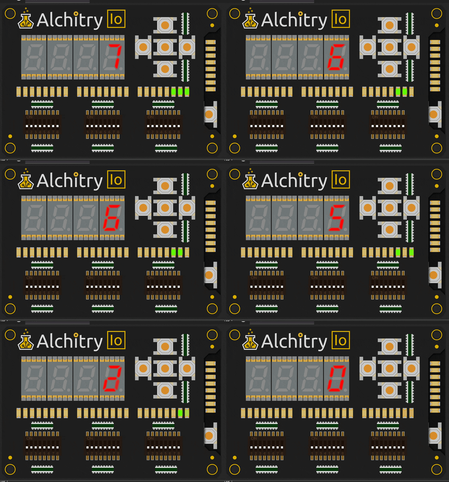
One common initial way to do this would be to slow the clock supply to the component supplying the countdown values.
Custom Countdown
The following simple code produces a countdown from INITIAL_VALUE to 0 and loop back again.
module custom_countdown#(
    INITIAL_VALUE = 7 : INITIAL_VALUE > 0
) (
    input clk,  // clock
    input rst,  // reset
    output out[$clog2(INITIAL_VALUE)]
) {

    dff value[$clog2(INITIAL_VALUE)](#INIT(INITIAL_VALUE), .clk(clk), .rst(rst))

    always {

        value.d = value.q - 1

        if (~|value.q){
            value.d = 7
        }

        out = value.q
    }
}
If we were to supply a slow_clk signal (generated from a counter) as the .clk input to this module, we would be able to achieve the effect:
// alchitry_top.luc

    .clk(clk) {
        // The reset conditioner is used to synchronize the reset signal to the FPGA
        // clock. This ensures the entire FPGA comes out of reset at the same time.
        reset_conditioner reset_cond
        .rst(rst){
            counter slow_clk(#SIZE(1), #DIV(CLOCK_DIVIDER))
        }
    }

    custom_countdown countdown(#INITIAL_VALUE(INITIAL_COUNTDOWN_VALUE), .rst(rst), .clk(slow_clk.value))
Unable to reset with board reset
The above arrangement will not reset the countdown module when the reset button is pressed.
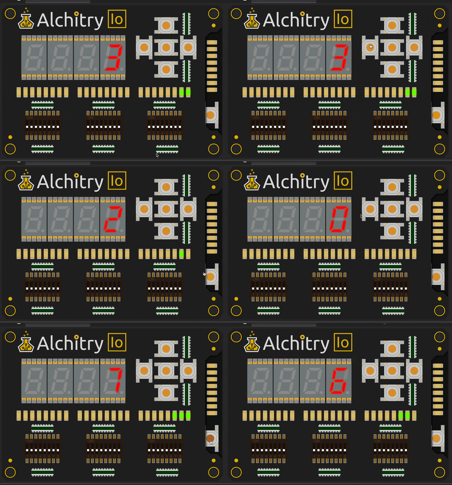
This will cause issues if you were expecting the board reset to reset all the components to the original value.
The reason why reset doesn’t work anymore is because the dff inside countdown module is no longer synchronised with the actual FPGA clock. The reset signal and all other modules (like the slowclock) are synchronised with the FPGA clock.
The slowclock produces a bunch of zeroes when reset button is pressed, and this stops countdown module from advancing – its like time is frozen for countdown when reset button is pressed.
Attempt 1: Add rst logic
The following line in custom_countdown.luc attempted to set content of dff value to 0 when rst is 1:
// custom_countdown.luc

        if (rst){
            value.d = 0
        }
However this still won’t work (won’t reset the content of dff value to 0) because slowclock signal is frozen (produces 0) for as long as rst == 1 (reset button is pressed). Hence nothing gets loaded to dff value.
Attempt 2: Use io_button[0] as manual reset button
Let’s try to use another button to trigger reset: io_button[0]:
// alchitry_top.luc

    .clk(clk) {
        reset_conditioner reset_cond
        button_conditioner io_button_0(#CLK_FREQ(CLK_FREQ), .in(io_button[0]))
        .rst(rst){
            counter slow_clk(#SIZE(1), #DIV(CLOCK_DIVIDER))
        }
    }

    custom_countdown countdown(#INITIAL_VALUE(INITIAL_COUNTDOWN_VALUE), .rst(io_button_0.out), .clk(slow_clk.value))
It kinda works, that is if we hold io_button[0] long enough, then the countdown is restarted back to 7. If we press the button rapidly, we might get lucky too:
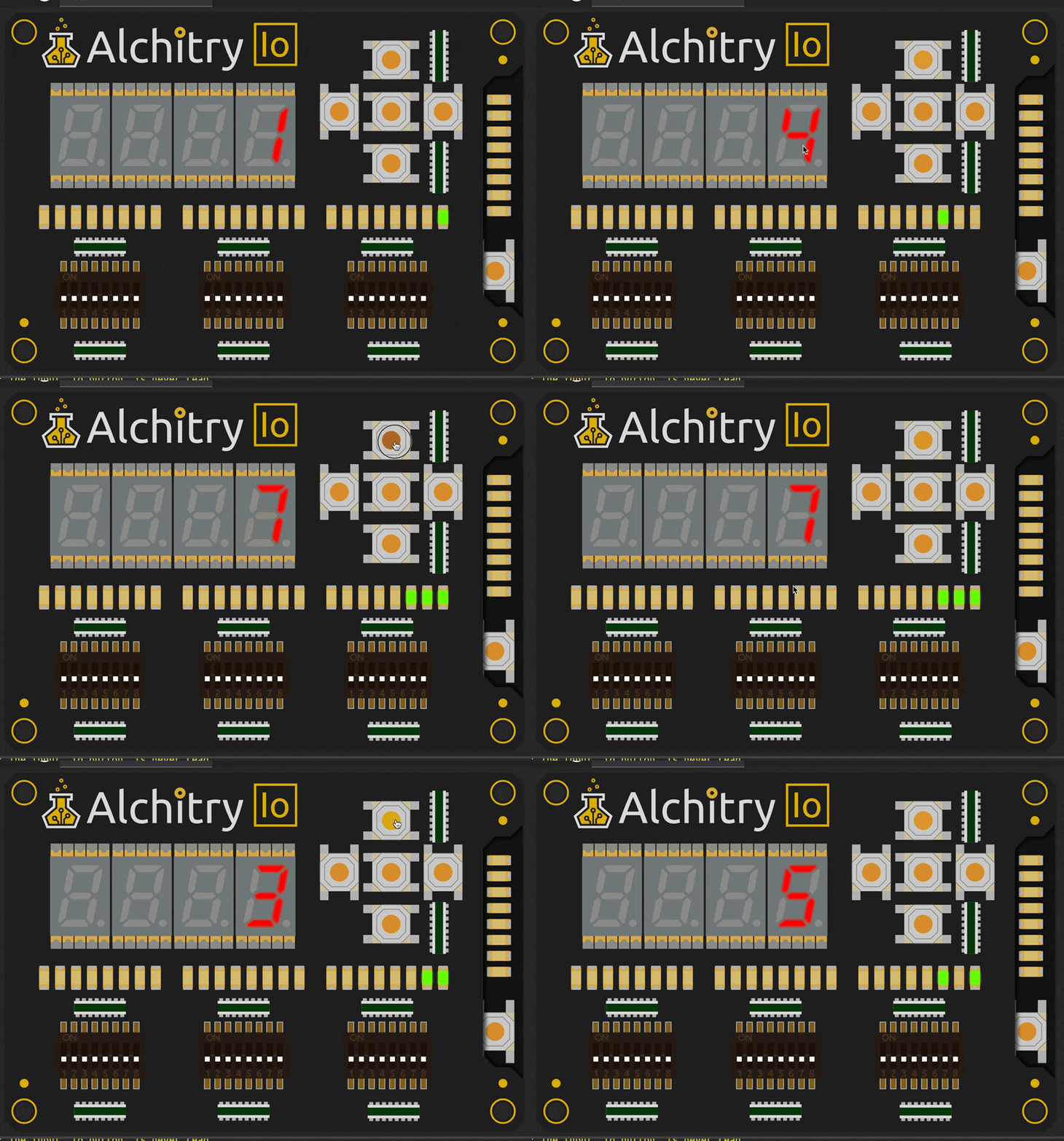
Manual Reset Issue in Attempt 2
Consider the following time plot of manual reset reset from pressing io_button[0], slowclk and actual FPGA clk:
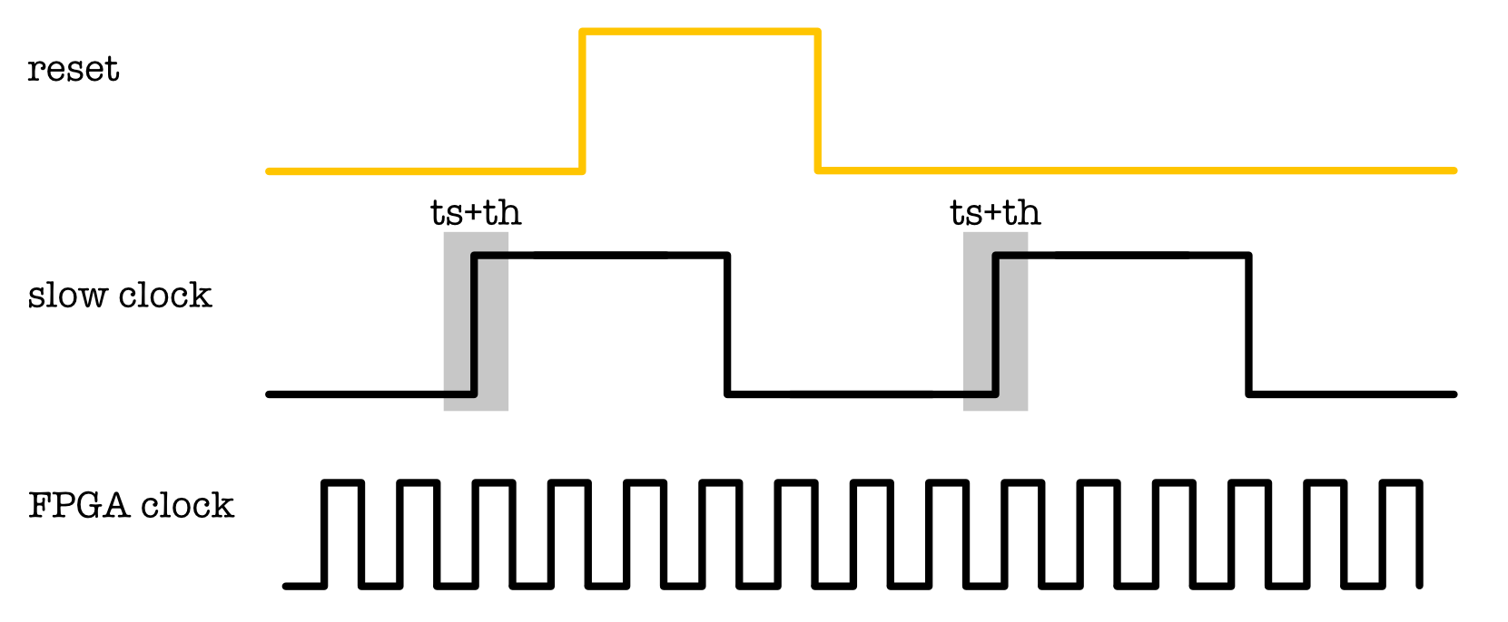
It is entirely possible for the slowclock (rising edge) to entirely miss the custom reset signal if the signal does not satisfy both ts and th of slowclock.
If custom reset happens to violate dynamic discipline (change at the shaded region th and ts), then we might run into metastability problem. Even worse, since we don’t know how button input from external source will change in relation to the rising edge of the clock (be it system or custom), it is possible that some dffs are reset and some others aren’t if you have multiple dffs in your project. This is disastrous!
Since external inputs are unreliable, it can be disastrous if it is used to trigger important events like a reset without conditioning. We need to rely on a better system called the Reset Conditioner.
Alchitry Reset Conditioner
The reset_conditioner component is provided by default in any project template created by the IDE. This component is responsible for two things:
- Synchronizes the reset button with the clock (FPGA
clk) to ensure proper timing. - Maintains the reset signal high for a minimum duration, ensuring a clean signal and synchronized FPGA reset.
The code is fairly simple:
// reset_conditioner.luc
module reset_conditioner #(
    STAGES = 4 : STAGES > 1 // number of stages
  )(
    input clk,  // clock
    input in,   // async reset
    output out  // snyc reset
  ) {

  dff stage[STAGES] (.clk(clk), .rst(in), #INIT(STAGESx{1}));

  always {
    stage.d = c{stage.q[STAGES-2:0],0};
    out = stage.q[STAGES-1];
  }
}
The reset conditioner works by leveraging the behavior of the dff chain to ensure the reset signal ends cleanly and synchronized with the clock. This module ensures that the reset signal lasts at least four clock cycles and ends synchronized with the clock.
- Initial Reset State: The raw reset signal (e.g., from a button press) is used to reset all the DFFs in the chain to
1. This forces the chain to output1across all stages. - Clocked Transition: Once the raw reset signal is released, the chain starts clocking through its default behavior:
- The first DFF always has a
0input. - On the first clock cycle after reset release, the first DFF transitions to
0, while the remaining DFFs still output1. - On each subsequent clock cycle, the
0propagates down the chain.
- The first DFF always has a
- Minimum Reset Duration: Because it takes four clock cycles for the
0to propagate through all four DFFs, the reset signal generated from this chain remains high (active) for at least four clock cycles, regardless of how briefly the user pressed the reset button. - Synchronized Reset End: The reset signal ends when the
0has propagated through all four DFFs, which is guaranteed to occur on a clock edge. This ensures that the reset signal transitions to0in sync with the clock.
By ensuring the reset signal ends on a clock edge, this mechanism prevents timing glitches or race conditions that could occur if the reset signal were to transition asynchronously relative to the clock (volates dynamic discipline).
This clever design is from Xilinx’s whitepaper: Get Smart About Reset: Think Local, Not Global.
Cost of using reset
In addition to covering the reset design, the whitepaper above also addresses the cost of using a reset.
Essentially, avoid connecting the reset signal to a
dffunless necessary, as it adds extra routing complexity and resource usage. In most cases, manydffvalues are irrelevant during a reset, as they are quickly assigned known values afterward.
Attempt 3: slowclk with Edge Detector
A better way to slow down the countdown module is to utilise slowclk with Edge Detector, then use conditional logic in the module, while keeping the clk signal as the original FPGA clk signal. This way, we can successfully reset the countdown module with FPGA’s reset button and synchronize the reset signal with any other components in the project.
The implementation can be found inside custom_countdown_v2.luc:
module custom_countdown_v2#(
    INITIAL_VALUE = 7 : INITIAL_VALUE > 0
) (
    input clk,  // clock
    input rst,  // reset
    input slow_clk,
    output out[$clog2(INITIAL_VALUE)]
) {

    edge_detector slow_clock_edge(#RISE(1), #FALL(0), .clk(clk), .in(slow_clk))
    dff value[$clog2(INITIAL_VALUE)](#INIT(INITIAL_VALUE), .clk(clk), .rst(rst))

    always {

		// conditional logic
        if (slow_clock_edge.out){
            value.d = value.q - 1
        }

        if (~|value.q){
            value.d = 7
        }

        out = value.q

    }
}
The clk input is connected to the original clk signal in alchitry_top.au:
custom_countdown_v2 countdown_v2(#INITIAL_VALUE(INITIAL_COUNTDOWN_VALUE), .rst(rst), .clk(clk), .slow_clk(slow_clk.value))
This way, we only decrement the content of dff value whenever we meet the rising edge of the slow_clock signal.
Why do we need the edge detector?
If we implement custom_countdown_v2 without the edge detector as follows, we will end up with this behavior:
// a sample without edge detector
module custom_countdown_v2#(
    INITIAL_VALUE = 7 : INITIAL_VALUE > 0
) (
    input clk,  // clock
    input rst,  // reset
    input slow_clk,
    output out[$clog2(INITIAL_VALUE)]
) {

    dff value[$clog2(INITIAL_VALUE)](#INIT(INITIAL_VALUE), .clk(clk), .rst(rst))

    always {

		// conditional logic without edge detector
        if (slow_clock){
            value.d = value.q - 1
        }

        if (~|value.q){
            value.d = 7
        }

        out = value.q

    }
}
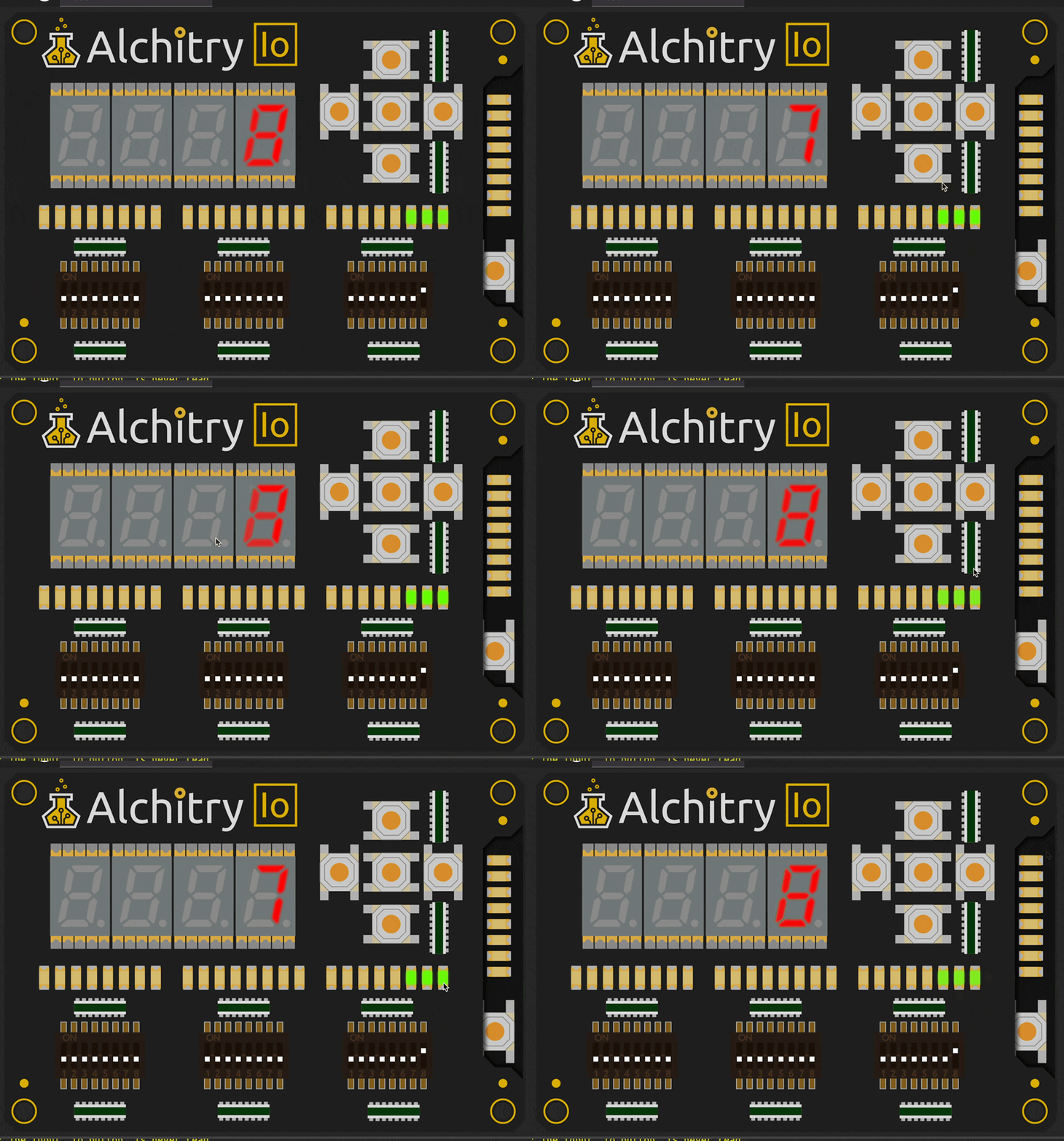
This is because slow_clock oscilates between 1 and 0 for multiple cycles of clk. Refer to this figure again:

Suppose one period of slow_clock lasts for 1000 periods of clk. During those 1000 clk cycles, the value of dff is continuously decremented by 1. However, since clk runs at 100 MHz by default (defined in the .acf constraint file), this decrement happens too quickly to be perceived by the human eye. To ensure the dff value is decremented exactly once every time slow_clock transitions from 0 to 1, we need an edge detector.
Summary
In this short tutorial, we learned about the importance of using reset_conditioner.
Our 1D project will be much larger than this sample project, consisting of many sequential logic components. We shall avoid the hassle of ensuring that all components in the project comes out of reset at once (and is properly reset). One way to do this is by ensuring that all sequential logic components run on the same clk signal, and then use additional logic in the body to slow down the perceived output.
Remember to utilise edge_detector (detect RISING, FALLING, or both edge) where appropriate, and not the raw slow_clk signal where appropriate. Since slow_clock operates at a much lower frequency than clk, devices running on clk should detect the edges of slow_clock rather than directly using its raw signal in conditional statements.
This ensures proper synchronization and avoids potential glitches or timing issues caused by directly sampling slow_clock.
 50.002 CS