 50.002 CS
- Overview
- Procedures and Functions
- Procedure Linkage and Stack
- Implementing Procedure Linkage Contract Using Stack
- An example with recursion
- Instruction Loading Address
- An Example with Multiple Arguments:
PUSHin reverse order - Tough Problems
- Summary
- Appendix
50.002 Computation Structures
Information Systems Technology and Design
Singapore University of Technology and Design
Stack and Procedures
You can find the lecture video here. You can also click on each header to bring you to the section of the video covering the subtopic.
Detailed Learning Objectives
- Defend Function Calls and Reusability
- Justify why functions are essential for code reusability and organization.
- Explain the basic structure and operation of functions, including passing parameters, returning values, and the call and return mechanism.
- Explain the Procedure Linkage and Stack Mechanism
- Explain the procedure linkage concept to manage function calls and returns efficiently.
- Explain the role of the stack in function calls, particularly in managing local variables, parameters, and return addresses.
- Discover Stack Operations
- Practice how to use stack operations like
PUSHandPOPto manage function call contexts.- Explain the importance of the stack pointer (SP), base pointer (BP), and linkage pointer (LP) in function execution.
- Discover Procedure Linkage Convention
- Explain the detailed procedure linkage convention, which dictates how functions should manage calling and returning from functions.
- List out the sequence of operations a function caller and callee must perform to ensure the correct execution flow and state preservation.
- Discover Stack Frame Management
- Explain how to allocate and deallocate stack frames to manage local variables and function arguments.
- Assess the impact of stack frame management on function calls, including nested calls and recursion.
- Analyze and draw the stack frame details of a recursive procedure call.
- Implement Functions with Multiple Arguments
- Explain how to handle functions with multiple arguments using the stack.
- Justify the sequence of stacking arguments in reverse order and the need for cleaning up the stack after function execution.
- Debug and Manage Function Calls
- Use debugging tools and techniques to inspect the call stack and understand function execution states.
- Summarize common pitfalls in function implementation, such as dangling references and stack mismanagement.
- Outline Advanced Topics in Procedure Linkage
- Describe advanced concepts like nested functions and non-local variables, and how they affect procedure linkage.
- Describe the limitations of C and C++ in handling complex function structures compared to languages like Python.
These objectives aim to equip us with a comprehensive understanding of how functions are implemented at a low level, using the stack for memory management during function calls and returns. We will also learn about the conventions and best practices in designing and debugging functions to write robust and maintainable code.
Overview
In the previous chapter, we learned the basics of how to naively compile C-language into \(\beta\) assembly language. \(\beta\) UASM provides a layer of abstraction such that we don’t need to bother ourselves with the details on how to load each and every bytes of instruction onto the memory unit, or keeping up with accounting matters such as physical memory addresses (we can replace these with labels instead).
In this chapter, we will learn about how to compile functions using the function call procedures, and how we can utilise the stack data structure for this. Both will allow us to have reusable code fragments which we normally know as functions that we can call as needed.
Procedures and Functions
Definition
A function is a fixed set of procedure / instructions. It is a reusable piece of instruction that we can repeatedly call with different parameters.
Motivation
Consider the following declaration and implementation of function fact below. It receives one argument int n, and returns an int.
int fact(int n){
	int r = 1;
	while (n > 0){
		r = r*n;
		n = n-1;
	}
	return r;
}
We can call it anywhere afterwards:
int result_1 = fact(4);
int result_2 = fact(9);
If we were to naively assemble this, we can translate this into the following \(\beta\) assembly source code:
.include beta.uasm
|| we call fact(4) first
LD(R31, n_1, R1)	| load 4 to R1
ADDC(R31, 1, R2)    | instantiate r

check_while_fact_4: CMPLT(R31, R1, R0)	| compute whether n_1 > 0
BNE(R0, while_true_fact_4, R31)	| if R0 != 0, go to while_true_fact_4
ST(R2, result_1, R31)	| store to result_1

|| then we call fact(9)
LD(R31, n_2, R1) 	| load 9 to R1, rewriting its old value
ADDC(R31, 1, R2)    | reset r

check_while_fact_9: CMPLT(R31, R1, R0)	| compute whether n_1 > 0
BNE(R0, while_true_fact_9, R31)	| if R0 != 0, go to while_true_fact_9
ST(R2, result_2, R31)	| store to result_2

HALT() | stop

while_true_fact_9: MUL(R1, R2, R2)	| r = r*n
SUBC(R1, 1, R1)	| n = n-1
BEQ(R31, check_while_fact_9, R31)	| always go back to check_while_fact_9


while_true_fact_4: MUL(R1, R2, R2)	| r = r*n
SUBC(R1, 1, R1)	| n = n-1
BEQ(R31, check_while_fact_4, R31)	| always go back to check_while_fact_4

n_1 : LONG(4)
n_2 : LONG(9)
result_1 : LONG(1)
result_2 : LONG(1)
Issues without Functions
There are a few issues here:
- The code is not scalable. What if we call the function
factmany more times as below? How long the assembly code is going to be?int result_1 = fact(4); int result_2 = fact(9); int result_3 = fact(20); int result_4 = fact(39); int result_5 = fact(18); int result_6 = fact(99); - There are so many repeated, boilerplate code. We are wasting memory (RAM) space.
while_true_fact_4andwhile_true_fact_9is technically identical for all 3 instructionsMUL,SUBC, andBEQ, only differ in the second argument ofBEQ: either branching tocheck_while_fact_4andcheck_while_fact_9.- Same issue with
check_while_fact_4andcheck_while_fact_9(theCMPLT,BNE, andSTinstructions)
- How do we know if we can overwrite the existing contents on any register
Rx?
In principle, a function:
- Is a callable, reusable series of instructions.
- Has a single named entry point. It means that we know the address of the first instruction of this function in memory.
- Is parameterizable (can access or receive a predefined number of arguments).
- Has local variables, which cannot be accessed anymore once the function returned.
Return Address and Return Value
Once a function returns, the CPU needs to know how to return to the caller, i.e: to know where is the return address of the caller, and then pass that return value to the caller.
For example, given this simple code:
int fact(int n){ --- (2)
	int r = 1;  --- (3)
	while (n > 0){ --- (4)
		r = r*n; --- (5)
		n = n-1; --- (6)
	}
	return r; --- (7)
}

int result_1 = fact(4); --- (1)
int result_2 = fact(9); --- (8)
We know that we need to execute fact twice, the first run with argument 4 and the second run with argument 9.
- The first line of instruction that is executed is labeled with (1) above. We then enter the function, executing the lines labeled as (2) to (7) in sequence.
- After (7), the CPU must know how to return to the caller, that is the address of instruction (1).
- Instruction (8) tells the CPU to enter the function again for the second run, thus executing (2) to (7) for another round, before finally stopping.
Procedure Linkage and Stack
Referring to the fact example in the previous section, notice a few accounting issues that we need to address in order to have a scalable and memory efficient function calls.
Basic Assumption
Before we proceed, assume we have a single CPU, and that the instructions are loaded to the Memory Unit from address
0and onwards sequentially,
We know that r and n are local variables within function fact. We can no longer access them, e.g: print them outside of the function. This means that we need to clean them up (from any storage unit) once the function returns.
We also need to establish a system where:
- The function can always access its arguments:
4and9for the first and second run respectively. - The function is expected to place a return value (if any) in a known memory location by the caller who will then access it
- The CPU can find the address of the caller, i.e: where instruction (8) is in memory.
Procedure Linkage Problem
These needs above become a problem that we need to solve if we want to have reusable segments of code. This is called the procedure linkage problem.
The procedure linkage problems that we need to solve are:
- We need to find a way to pass arguments into procedures
- Procedures need their own local variables (it’s own scope)
- Procedures need to be able to use the CPU registers without worrying about overwriting their original content.
- Procedures might need to call other procedures, including themselves (recursion)
Procedure Linkage Convention
These issues can be solved by establishing a kind of procedure linkage convention which explains how a function caller and the function itself (the callee) are linked to each other. We assume that the following is always obeyed whenever we are executing instructions within a function:
- Return value is always stored at
R0 - Arguments can be found in a dedicated space in the Memory Unit, called the Stack. The address of the top of the stack (first unused location) can always be found in
R29. The address of the base of the stack can always be found inR27. - Return address is always stored at
R28.
Special Registers Label
We label
R29asSP(Stack Pointer), andR27asBP(Base Pointer). We labelR28asLP(Linkage Pointer).
The function caller and the function itself (the callee) must obey a strict procedure that conforms to the procedure linkage convention. There are many different procedure linkage convention if we dive into the details (depending on how the compiler is made), but the general idea remain similar. Please abstract these ideas away as you learn this topic.
A function caller MUST obey the following sequence :
- Put arguments on the stack
- Branch to the target function, leaving return address in
LP - Remove arguments on stack upon return
- Obtain return value from
R0(if any)
A callee (the function itself) MUST obey the following sequence :
- Perform promised computation
- Leave result in
R0(if any) - Leave the state of all registers in REGFILE except
R0unchanged upon returning to the caller. - Leave stack data unchanged upon returning to the caller.
The “Stack” implementation
In general, a stack is a type of data structure where you can perform two essential operations: PUSH and POP. Its principle is last-in-first-out.
Stack Recap
You always add item via
PUSHoperation to the top of the stack, and can only remove the topmost item in succession viaPOPoperation from the top of the stack.
How do we implement the stack data structure to aid our function execution?
Decide the Stack Space
We reserve an arbitrary (unused/free) block of location in our Memory Unit to be space for the stack. Illustrated below is a block of memory unit from address 0x010C to 0x0128 reserved as our stack:
![]()
We have these conventions as mentioned above:
R29 (SP)contains the address of the top of the stack (available location to write to).- Memory addresses are illustrated to be increasing downwards, hence our stack grows downwards.
We can PUSH (add data) to the stack via these two instructions:
ADDC(SP, 4, SP)(increaseSP’s content by4so that it points to the next line address)ST(Rx, -4, SP)(store content of chosen registerRxto address pointed byReg[SP]-4).
To POP (remove data) from the stack, we can do so via these two instructions:
LD(SP , -4, Rx)(load the content pointed byReg[SP]-4to a chosenRx)SUBC(SP, 4, SP)(decreaseSP’s content by4so that it points to the previous line address)
In \(\beta\) uasm, we simply create these macros for PUSH and POP:
PUSH(Rx): pushReg[Rx]onto the stackPOP(Rx): pop the value on top of the stack toReg[Rx]
And also the following macros for easier stack management which will be explained more later:
ALLOCATE(k) : ADDC(SP, 4*k, SP). This moves the pointer to the top of the stack “down” (increased memory address).DEALLOCATE(k) : SUBC(SP, 4*k, SP). This moves the pointer to the top of the stack “up” (decreased memory address).
Allocating a Stack Space
The content of
SPcontains the address of the memory which we define as the top of the stack.ALLOCATEis used to moveReg[SP]to a free memory location that will be used as start of the stack. Obviously, you won’t want to overwrite the part of your memory containing important information like your program instructions or data with stack data.
Example of stack usage
Allocating the stack
Assuming the initial content of SP is 0, then in order for SP to point to the address 0x010C shown in the figure above, we can write:
.include beta.uasm

ALLOCATE(67)
ADDC(R31, 5, R1) | instructions
| other instructions
0x10C is 268 in decimal. Since macro ALLOCATE will multiply the input by 4 before storing it at SP, we need to put 268/4=67 as the input to ALLOCATE.
This is done to tell the CPU that the stack starts at address 0x010C onwards, so that whatever content stored in the earlier addresses will not be overwritten by the stack.
What if we don’t
ALLOCATE?The stack will start at address 0. Typically what is stored address
0is the first executable instruction (i.e: the beginning of our program). We usually don’t want to overwrite any instructions.
Adding items to the stack
Suppose we put the following values: 16, 17, 18 to R1, R2, and R3 respectively:
ADDC(R31, 16, R1)
ADDC(R31, 17, R2)
ADDC(R31, 18, R3)
We can put these values into the stack using:
PUSH(R1)
PUSH(R2)
PUSH(R3)
Upon execution of these series of instruction, the state of the stack is:

Notice that the “top” of the stack is at the bottom, and that the stack grows downwards by convention because we illustrate larger memory addresses to be at the bottom of the diagram.
Familiarize yourself and get used to tracking the “state” of the stack,
PC, and all registers in the REGFILE after executing each line of instruction .
Now suppose we use R1, R2, R3 for other stuffs and overwrite its values:
MULC(R1, 2, R1)
MULC(R2, 3, R2)
MULC(R3, 4, R3)
The new state of the registers are now written in red. The stack stays the same, and so does SP.
We can now say that the stack contains the old value of the registers R1, R2, R3, as shown:

Removing items from the stack
To remove items from the top of the stack, we can use POP instruction:
POP(R3)
POP(R2)
POP(R1)
The state of the stack and the registers is therefore as shown. Notice how POP instructions can be used to restore the registers state to before as in Step 1.
Garbage Values
The remnants of data that was pushed to the stack actually stays in memory, but its rendered irrelevant because it can be overwritten again by other instructions (hence space is seen as freed).
In fact, there’s no such thing as erasing contents in the memory unit in the physical world, unless we explicitly write a bunch of zeroes to make it disappear. We simply always overwrite them. It’s unlike scrubbing away pencil drawings.

Resetting the stack
Finally, we reset a stack by simply changing the value SP. For example, we can return the state of SP to 0 as it was before Step 1.
DEALLOCATE(67)
This allows whatever that was at address 0x10C or 268 to be overwritten, effectively “clearing” the memory.
Try!
There’s no point staring at these assembly data. Try out these instructions in
bsim, and observe the state of the stack and registers after executing each instruction as practice.
The activation stack
When you use a debugger, notice how there exist something called the call stack:
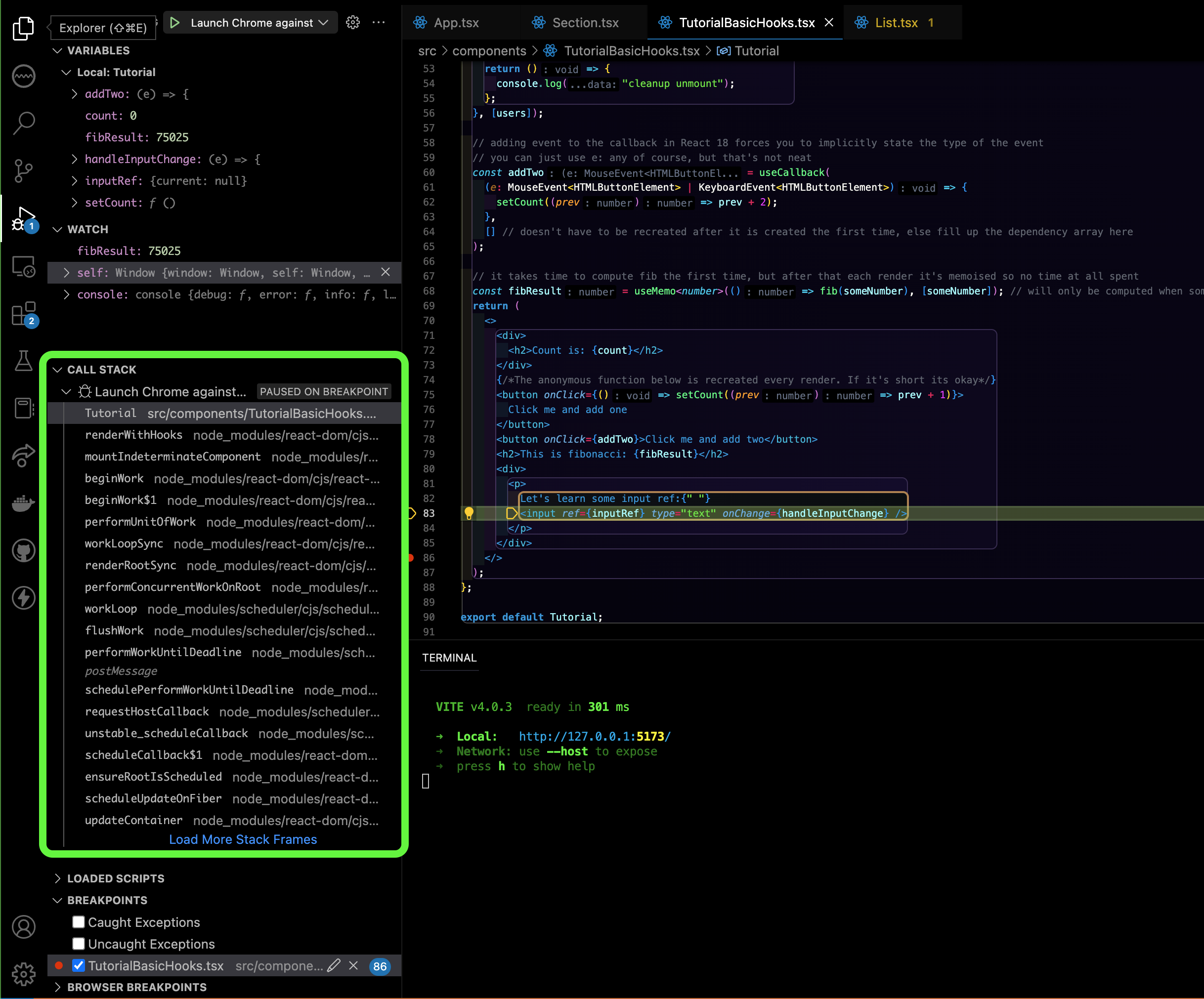
This is also known as the activation stack. Within the activation stack, we have many activation records (one per function).
Activation Stack and Activation Record
The activation stack is where the run time environment of the program keeps track of all the functions that have been called. It stores many activation records, which store all the necessary information about a function call, including parameters, local variables, return values, location currently being executed in the function, etc. An activation record is pushed into the stack when a procedure is called and it is popped when the control returns to the caller function.
Implementing Procedure Linkage Contract Using Stack
Function Caller Procedure
A (function) caller must obey the following calling sequence:
- Put arguments on the stack in reverse order, meaning that last argument is pushed first and the first argument is pushed last.
- Branch to the target function, leaving return address in
LP - Remove arguments on stack upon return of the callee. This can be done using
DEALLOCATE(N)whereNis the number of arguments - Obtain return value from
R0(if any), for example:ST(R0, location, Rx)
Let’s use our factorial function to illustrate each of these steps:
int fact(int n){
	int r = 1;
	while (n > 0){
		r = r*n;
		n = n-1;
	}
	return r;
}

int result_1 = fact(4) -- (first call)
int result_2 = fact(9) -- (second call)
The function fact is called twice, so we have two callers. We can hand assemble the first caller following the caller procedure above.
Firstly, Allocate some memory space for caller variables and instructions
To allocate memory space for global variables, we can use any of the following methods (it’s up to the compiler programmer’s discretion):
- Write them below all of the instructions
- Write them above of all the instructions, but since
PCstarts at0, we can’t execute “variables”. We need the first instruction toBRANCHto the address of the first line of instruction. - Use the
.operator to load them at the desired memory location, e.g:0x01B0- Define labels and its values
- Then, redirect the instruction back at address
0using the.operator again
To allocate memory space for instructions (i.e: make SP point to some unused memory location), we can use ALLOCATE. The example below shows how we can use the . operator to declare certain memory locations to hold the values for these global variables: result_1, result_2.
.include beta.uasm
. = 0x01B0 | load values at fixed location
result_1 : LONG(0)
result_2 : LONG(0)

. = 0x0000 | load instructions from address 0 onwards
ALLOCATE(50)
Secondly, Implement calling sequence
We assume that fact is a label that contains the address of the first instruction of the factorial function.
There are four parts of the calling sequence:
|| Calling sequence
ADDC(R31, 4, R1) | put 4 to R1

|| (1) put argument on the stack
PUSH(R1)

|| (2) branch to the function, storing return address at LP
BEQ(R31, fact, LP)

|| (3) remove argument from stack after function returns
DEALLOCATE(1)

|| (4) obtain return value at R0 and store it elsewhere (you can also move it to another Register)
ST(R0, result_1, R31)
HALT()
Function Callee Procedures
Thirdly, Implement callee entry sequence and function computation (body of the function)
Properties of Callee Sequences
A callee must adhere to the following properties:
- Leave the state of all registers in REGFILE except
R0unchanged upon returning to the caller.- Leave stack data unchanged upon returning to the caller.
The callee sequences has two parts: callee entry sequence and callee exit/return sequence.
The entry sequence is consisted of five steps:
PUSH(LP): to preserve the state ofLPwhich contains the return address to the caller of this function.PUSH(BP): to preserve the state ofReg[R27]ADD(SP, R31, BP): move the content ofSPtoBP. This is to set the stack frame base for this function call. Note that we have a convenient Beta macro for this:MOVE(SP, BP)- Push all registers that we will use for the computation (except
R0) - Load arguments from the stack
Afterwards, we then proceed with actually implementing the function (this is the actual work).
Continuing our assembly code, writing Step 1 to Step 3 of the entry procedure is straightforward.
|| Callee entry sequence
fact: PUSH(LP) | (1)
PUSH(BP) | (2)
MOVE(SP, BP) | (3)
Now to figure out Step (4), we need to know the registers that we will use for computation of fact.
Recall the implementation of the function fact:
|| Assume (value of) n in R1 and (value of) r in R2
check_while_fact: CMPLT(R31, R1, R0)
BNE(R0, while_true_fact, R31)
BEQ(R31, done, R31)

while_true_fact: MUL(R1, R2, R2)
SUBC(R1, 1, R1)
BEQ(R31, check_while_fact, R31)
We can see that the registers that are used for the computation (apart from R0) are : R1 and R2
Reminder about R31
You don’t need to preserve the value of
R31as it is a constant. Its value is always0and you cannot rewrite new values into it.
Therefore Step 4 should involve PUSH of any registers that will be used for this function’s computation:
|| (4) Push the contents of all registers we will use for the computations onto to stack to preserve its old value
PUSH(R1)
PUSH(R2)
Think!
Why do we need to
PUSH(which is equivalent to preserving) the value of registers that are about to be used by this callee/function?
Then in Step 5, we load the argument n onto R1, and put 1 in R2. R1 holds the value of n and R2 holds the value of r.
|| (5) get arguments.
LD(BP, -12, R1) | Note: the first argument is at memory address BP-12
ADDC(R31, 1, R2)
Afterwards, we can continue with the implementation of fact above as it is.
Think about
Reg[BP]-12!Think carefully about why the first argument is always at address pointed by
Reg[BP]-12. This is a direct result of caller procedure and callee entry sequence (1) to (3).
Fourthly, Implement callee exit sequence
The exit sequence is consisted of six steps:
- Put return value at
R0. - Restore all registers’ state that were used by the function computations using
POP, in reverse order. ADD(BP, R31, SP): move the content ofBPtoSP. This is to set the stack pointer back to the stack frame base for this function call.Remember, we need to leave the stack state as per the original state when the function returns. Hence, whatever stuffs that are added to the stack by this function must be removed.
We can also use the macro for this:
MOVE(BP, SP)POP(BP): restoreReg[BP]to its original valuePOP(LP): restoreReg[LP]to its original value – remember, this register contains the caller’s return address.JMP(LP, R31): return to the caller.
Let’s write them out in assembly, continuing our fact example above:
|| (1) put return value r (originally in R2) at R0
done: ADD(R2, R31, R0)

|| (2) restore register contents
POP(R2)
POP(R1)

MOVE(BP, SP) | (3)
POP(BP) | (4)
POP(LP) | (5)
JMP(LP, R31) | (6)
Think!
Why do we need to “clear” the callee stack when it returns to the caller?
Reusing Functions
Now to call fact for the second time, we can simply write another calling sequence. The fact instructions remain intact and reusable.
Combining everything, we have:
.include beta.uasm

||| Space allocation for variables and instructions (set start of stack)
. = 0x01B0 | load values at fixed location
result_1 : LONG(0)
result_2 : LONG(0)

. = 0x0000 | load instructions from address 0 onwards
ALLOCATE(50)

||| First caller "calling sequence" -- fact(4)
ADDC(R31, 4, R1) | put 4 to R1
PUSH(R1) | step (1)
BEQ(R31, fact, LP) | step (2)
DEALLOCATE(1) | step (3)
ST(R0, result_1, R31) | step (4)

||| Second caller "calling sequence" -- fact(9)
ADDC(R31, 9, R1) | put 9 to R1
PUSH(R1) | step (1)
BEQ(R31, fact, LP) | step (2)
DEALLOCATE(1) | step (3)
ST(R0, result_2, R31) | step (4)
HALT()

||| Callee entry sequence
fact: PUSH(LP) | step (1)
PUSH(BP) | step (2)
MOVE(SP, BP) |  step (3)

| step (4)
PUSH(R1) | n
PUSH(R2) | r

LD(BP, -12, R1) | step (5)
ADDC(R31, 1, R2)

||| Computation
check_while_fact: CMPLT(R31, R1, R0)
BNE(R0, while_true_fact, R31)
BEQ(R31, done, R31)

while_true_fact: MUL(R1, R2, R2)
SUBC(R1, 1, R1)
BEQ(R31, check_while_fact, R31)

||| Callee exit (return) sequence
done: ADD(R2, R31, R0) | step (1)
POP(R2) | step (2)
POP(R1)

MOVE(BP, SP) | step (3)
POP(BP) | step (4)
POP(LP) | step (5)
JMP(LP,R31) | step (6)
Once again, please run the program in bsim step by step. At each instruction, pay attention on the state of all registers, the stack, and PC.
In this course, you are expected to mentally execute each instruction line by line and give the state of all registers involved, the PC, and the stack at all times during examination. Lots of practice is definitely needed.
At the end of the program, you should see that you have each answer in the memory address 0x01B0 and 0x01B4:

An example with recursion
We can also implement fact recursively:
int fact(int n){
	if (n > 1){
		return n * fact(n-1);
	}
	return 1;
}

int result_1 = fact(3);
The recursive function fact can be hand assembled into:
||| callee entry procedure
fact: PUSH(LP)
PUSH(BP)
MOVE(SP, BP)

| Preserve old register values before using them
PUSH(R1)	| n
PUSH(R2)	| temp reg
PUSH(R3)	| temp reg
PUSH(R4) 	| for constant

LD(BP, -12, R1) | get first argument
ADDC(R31, 1, R4) | put 1 to R4 as a constant

||| Computation Part 1
begin_fact_check: CMPLT(R4, R1, R2) | compare if 1 < n, store in R2
BNE(R2, if_true, R31)
|| leave 1 in R0
ADDC(R31, 1, R0)

||| Callee exit sequence
exit_sequence: POP(R4) | Pop registers in reverse order, to restore each old register value
POP(R3)
POP(R2)
POP(R1)

MOVE(BP, SP)
POP(BP)
POP(LP)
JMP(LP, R31)

||| Computation Part 2
if_true: SUBC(R1, 1, R3) | compute n-1, store at R3

||| Recursive calling sequence
PUSH(R3)
BEQ(R31, fact, LP) | recurse

|| remove unused argument from stack when recursion returns
DEALLOCATE(1)

|| compute n * fact(n-1), store at R0 before returning
MUL(R0, R1, R0)

BEQ(R31, exit_sequence, R31) | return
The calling sequence is simple:
.include beta.uasm

ALLOCATE(100)

ADDC(R31, 3, R1)
PUSH(R1)
BEQ(R31, fact, LP) | call fact(3)
DEALLOCATE(1)
HALT()
Breakpoint
You can add
.breakpointin the code to allow for debugging, and inspect the stack frame for each function call.
In this example, calling fact(3) will cause fact(2), and fact(1) to be called recursively.
Stackframe State
The state of the stack frame right before fact(3) branching, right before fact(2) branching, right before fact(1) branching, and right before fact(1)calls its exit_sequence is as follows:

Notice several properties:
- The stack size for each callee frame is constant.
- In this example, it is 7 words (1 word is 32 bits).
- This is caused by 1 argument
PUSH, twoPUSHfrom callee entry sequence, and fourPUSHof registers (to be used for computation).
- The current
BPandSP(rendered in black) points to the base and the top of the stack of the current caller.
Base of the stack is not the start of the stack frame. It is defined as the location of the first item pushed into the stack by that caller after MOVE(SP, BP) step.
- The location of the argument for the current callee is always 3 words above the location pointed by the current
BP.- It is the address pointed by the current
BPsubtracted by 12 (bytes).
- It is the address pointed by the current
- The return address of the current caller is always placed after the argument in the stack.
- This is the direct result of
PUSH(LP)as the first instruction in the callee entry sequence. - For example, the return address for the first
factcall:fact(3)is at0x0014(just look at the lower 16 bits for simplicity). - This is the address of instruction:
DEALLOCATE(1)(see next section to understand why this is so).
- This is the direct result of
Again, test your understanding and sharpen your skills by mentally running each instruction one by one from the top and be aware of the current instruction, stack state, PC state, and register states at all times.
Instruction Loading Address
To compute the address of each instruction, we can assume (if not given) that the address of the first instruction is at 0x0000.
- Recall that each \(\beta\) instruction is 32 bits long (4 bytes).
- Therefore, the address of subsequent instructions are always increased by 4.
For instance, if we simply load this instruction into the memory unit starting from address 0x0000:
.include beta.uasm

ALLOCATE(100)

ADDC(R31, 3, R1)
PUSH(R1)
BEQ(R31, fact, LP) | call fact(3)
DEALLOCATE(1)
HALT()

||| callee entry procedure
fact: PUSH(LP)
PUSH(BP)
MOVE(SP, BP)

...
It will obtain the following addresses:

This screenshot is taken from bsim just before we branch to fact for the first time with argument 3. That is why the PC is pointing to address 0x0010.
Notice that as mentioned, the address of instruction DEALLOCATE(1) (macro for SUBC(SP, 4, SP)) is 0x0014.
An Example with Multiple Arguments: PUSH in reverse order
Consider the following function with multiple arguments:
int y(int m, int x, int c){
	return m*x + c;
}

int result = y(2, 5, 3);
In order to call this function, we need to push each argument in the reverse order to the stack, before calling (branching) to this function. That is, last argument is pushed first, and the first argument is pushed last:
.include beta.uasm
. = 0x0CC
result: LONG(0)

. = 0x000
ADDC(R31, 2, R1) | first argument
ADDC(R31, 5, R2) | second argument
ADDC(R31, 3, R3) | third argument

|| Calling Sequence
|| Push arguments in the reverse order
PUSH(R3) | push third argument first
PUSH(R2) | then push second argument
PUSH(R1) | finally push the first argument last

|| Branch to the function
BEQ(R31, y, LP)
|| Deallocate the arguments
DEALLOCATE(3)
|| Store return value
ST(R0, result, R31)
HALT()
Then in the function y, we obtain the arguments sequentially, starting from BP-12 for the first argument, BP-16 for the second argument, and so on:
||| Callee entry sequence
y : PUSH(LP)
PUSH(BP)
MOVE(SP, BP)

| Preserve old register values before using them
PUSH(R1)
PUSH(R2)
PUSH(R3)

| Load arguments
LD(BP, -12, R1) | m
LD(BP, -16, R2) | x
LD(BP, -20, R3) | c

| Computation
MUL(R1, R2, R1)
ADD(R1, R3, R0) | leave the answer at R0

||| Callee exit sequence
| Return all register values (POP in reverse order)
POP(R3)
POP(R2)
POP(R1)

MOVE(BP, SP)
POP(BP)
POP(LP)
JMP(LP, R31)
The reason we PUSH arguments into the stack in the reverse order: last argument first, first argument last, is so that BP-12 will consistently be the first argument regardless of how many arguments this function has. This convention makes it easier for the compiler. To access other argument i, we simply load from BP-4*(i+2).
Tough Problems
The procedure linkage that we have just learned above works in general, but it doesn’t really solve all problems.
Problem 1: Nested procedure definitions
In Python, we can define nested procedure as follows:
def f(x):
	def g(y):
		return x+y;
	return g
This requires g to access non-local variable x. We would require some kind of “static-links” in stack frames. The C programs avoids this problem by outlawing nested procedure declarations.
Problem 2: Dangling references
int *p; /* a pointer */
int h(x) {
	int y = x*3;
	p = &y;  // set p to be pointing to address of y, a local variable
	return 37;
	}
h(10);
print(*p);
The C-code above will compile, but when executed, unexpected behavior can happen: program crash (segmentation fault), random stuffs being printed, etc.
Why is Python considered “beginner friendly”
With C/C++, life is harsh and it is the responsibility of the programmer to ensure that mistakes like these do not happen.
Python on the other hand will babysit and protect us from these mistakes, as there’s language restriction that forbids constructs that could lead to dangling references (we are also given automatic storage management, and lots of things are taken care of – garbage collection, variables allocation, etc).
Summary
You may want to watch the post lecture videos here:
The concepts of stacks and procedures are fundamental in understanding how modern computers execute programs, particularly how they handle function calls and manage memory. Here are they key points from this notes:
- Stack Operations: The stack is a LIFO (Last In, First Out) data structure used extensively in programming for managing function calls, local variables, and return addresses. Common stack operations include
PUSH, which adds an item to the top of the stack, andPOP, which removes the top item from the stack. We set aside an unused memory region for function calls. Before calling any function, it is extremely important to change the content ofSP(reserved stack pointer register) to reflect a free memory address (signifying the beginning of the stack). - Procedure Calls: When a procedure (or function) is called, the return address (the address in the program where control should return after the procedure is finished) and sometimes the parameters are pushed onto the stack. The stack helps in keeping track of point of execution especially when procedures are nested or called recursively.
- Stack Frame: Each function call creates a new stack frame or activation record at the top of the stack. This frame typically contains the function’s return address, its parameters, and its local variables. The stack pointer (SP) and base pointer (BP) are used to manage and access elements within the current stack frame effectively.
- Handling of Arguments and Return Values: Arguments to functions are typically passed using the stack, where they are pushed before the function call and popped off by the called function. Return values are generally placed in a designated register or location on the stack.
- Procedure Linkage: This involves the conventions that control the entry and exit sequences of functions, ensuring that the return address is properly managed and that the stack remains balanced (i.e., it has the same depth at function entry and exit).The calling and callee sequence mentioned above are designed such that we have a fixed convention for linking procedures. The data structure needed for procedure linkage is a stack, and it can simply be implemented using macroinstructions:
PUSHandPOPon some unused memory block, which address is stored in registerR29: SP. - Special Registers:
R29(the SP register) points to a free space signifying the top of the stack. There are also two other reserve registers:R27: BPandR28: LP.BPis used as a reference to obtain function argument, whileLPholds the return address. - Cleanup: The callee has to leave stack data unchanged upon returning to the caller, that is to clear whatever data that was put in the stack during its execution. As a result, we might find dangling pointers: pointer that points to an address that is no longer used when we try to access a function’s local variable long after the function has returned.
These elements are critical for managing data in a structured way during program execution, supporting the nested and recursive function calls that are common in modern programming. Understanding how stacks and procedures operate is crucial for debugging and optimizing software, as well as understanding low-level execution flow within a program.
Appendix
About the PC
This section is a deep dive to appreciate the dynamic discipline of the regfile. You can skip it if you want.
We have learned before that PC register always contain the address of the next instruction to be executed.
There’s one subtle point to realise: when the PC is currently pointing to an address A, the instruction at A is actually already computed computed in the current cycle, but the result (of this computation) hasn’t been stored, yet. The result will only be stored (in some register or memory address) only in the next cycle.
Dynamic Discipline of the REGFILE
Remember that memory write is synchronized with the clock. See this section if you forgot.
Take for example this particular execution state in the \(\beta\) CPU:

The current content of register PC is 0x004, that is where instruction: ADDC(R31, 3, R1) resides. The output of ADDC has already been computed in this cycle, as denoted in the blue value at the output port of the ALU: 0x00000003.
- All values in blue are computed values (in this cycle) due to this current instruction
ADDC.
However, notice Reg[R1] still contains 0 and not the new result 3 yet. In this cycle, we are still trying to write 3 into R1.
Only at the next cycle,Reg[R1] finally stores the new value 3. The figure below shows the state of the \(\beta\) CPU at the following cycle:

Therefore, what we actually mean when we say that the PC always point to the next instruction executed is precisely that the result will only be synchronized in the next cycle (but computation is done in the current cycle).
Don’t worry too much about it. It’s just some subtle detail to appreciate.