 50.002 CS
50.002 FPGA Tutorials
We are using Alchitry Au FPGA Development Board in this course. To facilitate learning and development, we purchased the Br breakout board (prototyping periphery) and the Io expansion board.
It is crucial that you start familiarising yourself with coding the FPGA right away after you obtain the kit. Failure to do so will result in inevitable sufferings towards the end of the semester, which we do not want you to go through. This is unlike any programming subjects that you have learned in previous terms.
The FPGA tutorials are written in Lucid programming language, specifically Lucid V2 programming language.
- Product description, schematics for: Au, Io, and Br.
- The Br reference schematic is different from original Alchitry due to our custom PCB. Use our NEW one here.
- Please DO NOT use Alchitry original Br, the schematic is DIFFERENT (see below)
- Lucid V2 documentation: : We will program the FPGA using Lucid, not Verilog. However, you can choose to program it using Verilog if you have prior experience.
Beginner Tutorials
Consult these tutorials by Alchitry to get started:
- Background tutorial
- Your First FPGA Project and external IO setup
- Synchronous Logic (Related to Week 3 materials)
- Io Element Project
- ROM and FSMs Project (Related to Week 2-5 materials)
- Basic CPU (Related to Beta CPU)
- DDR3 RAM (intermediate)
Recommended Tutorials
Consult these tutorials based on your needs:
I/O Drivers
Driving LED displays efficiently requires understanding various communication protocols and hardware interfaces. In this guide, we will explore how to control WS2812B addressable LEDs, HUB75 RGB LED matrices, 74HC595 shift registers, and MAX7219 LED drivers using an FPGA.
-
WS2812B (Addressable RGB LEDs)
WS2812B LEDs are individually addressable RGB LEDs with an integrated driver chip. They use a single-wire timing-based protocol to transmit color data in a daisy-chain fashion. Since precise timing is required, controlling WS2812B from an FPGA involves generating accurate pulse widths to match the protocol specifications. -
HUB75 RGB LED Matrix
The HUB75 interface is commonly used in large RGB LED panel displays. It utilizes a multiplexed row-column addressing scheme, requiring multiple control signals, including row selection, RGB data lines, and clock signals. Driving a HUB75 matrix with an FPGA involves sequentially scanning rows while updating pixel data at high speed to achieve a flicker-free display. -
74HC595 Shift Register
The 74HC595 is an 8-bit serial-in, parallel-out shift register used for expanding output pins. It is often used in LED matrix displays to control multiple LEDs with fewer FPGA I/O pins. The FPGA shifts data into the register using a serial clock (SCK) and latch enable (LE) signal, allowing efficient control of large LED arrays. -
MAX7219 LED Driver
The MAX7219 is a serially interfaced LED driver designed for controlling 7-segment displays, dot matrices, and bar graphs. It simplifies driving multiple LEDs by handling current regulation and multiplexing internally. Communication with the MAX7219 is done using a simple SPI-like protocol, making it an efficient solution for driving multiple digits or LED segments with minimal FPGA resources. -
VGA: The VGA interface drives a monitor by outputting analog RGB signals along with HSYNC and VSYNC pulses at precise timings. A VGA driver in text mode divides the 640x480 visible area into character cells, looks up each cell’s character and color from a memory buffer, and uses a font ROM to determine per-pixel ink or background color. Because the RGB output is combinational and the memory is shared with the CPU, careful attention must be paid to clock domain multiplexing, memory read latency, and pipelined address lookahead to ensure the correct pixel data is displayed at the right time.
Each of these devices requires a different approach to interfacing with an FPGA.
You can refer to these repositories for demos of following drivers in LucidV2 & its guide:
If you’re looking for 1D project sample for 50.002 in LucidV2, checkout this repository.
Br Board Schematic
This is our Br Board schematic:
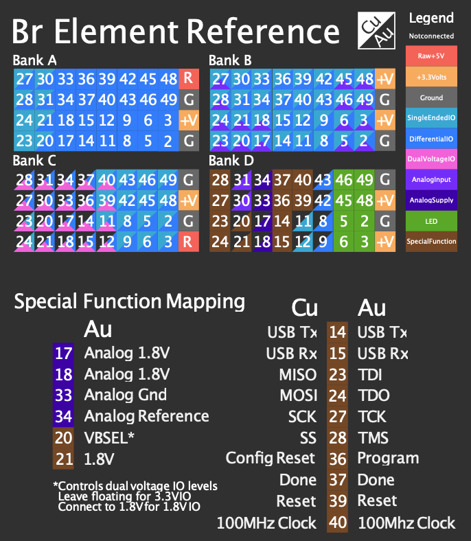
Notice how it is different from the schematic uploaded on Sparkfun:
