 50.002 CS
- Combinational Logic Foundations
- Implementation
- First Principles Before Generalisation
- Module Array Indexing in Verilog
- Do NOT use
instance.output_port(hierarchical references) in Verilog - Summary
50.002 Computation Structures
Information Systems Technology and Design
Singapore University of Technology and Design
(Verilog) Lab 2: Combinational Logic
This is a Verilog parallel (Verilog-2005 used) of the Lucid + Alchitry Labs Lab 2. It is not part of the syllabus, and it is written for interested students only. You still need to complete all necessary checkoffs in Lucid, as stated in the original lab handout.
If you are reading this document, we assume that you have already read Lab 2 Lucid version, as some generic details are not repeated. This lab has the same objectives and related class materials so we will not paste them again here. For submission criteria, refer to the original lab 2 handout.
Combinational Logic Foundations
Before touching the FPGA, we will translate several logic requirements into Boolean expressions and circuits. Afterwards, we will describe that hardware in HDL and run it on the Alchitry lab simulator. If all works well, we shall build and flash it to the FPGA.
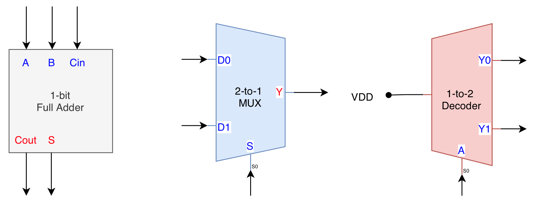
In this lab, we will build three core combinational logic devices: the full adder, the multiplexer (both 2 to 1 and 4 to 1), and the decoder (both 1 to 2 and 2 to 4).
We will dive straight into its implementation in this Verilog version.
Decoder:
\[\begin{align} \text{1-to-2:}\quad &Y_0 = \overline{A}, Y_1 = A \\ \text{2-to-4}:\quad &Y_0 = \overline{A}\overline{B},\space Y_1 = \overline{A}B,\space Y_2 = A\overline{B},\space Y_3 = AB \end{align}\]Multiplexer:
\[\begin{align} \text{2-to-1:}\quad &Y = \overline{S}D_0 + SD_1 \\ \text{4-to-1:}\quad &Y = \overline{S_1}\overline{S_0}D_0 + \overline{S_1}S_0D_1 + S_1\overline{S_0}D_2 + S_1S_0D_3 \end{align}\]Implementation
We will build the modules in the following order:
- Full adder
- N-bit adder using full adder
- Mux2
- Mux4 using Mux2
- Decoder1to
- Decoder2to4 using Decoder1to2
For each module, we also provide a testbench for you and the expected outcome.
Files and folder layout
Create this structure:
lab2_verilog/
  src/
  test/
Then you can compile and run with iverilog -g2005 and vvp as usual.
1-bit Full Adder
You are NOT allowed to use the built-in ‘+’ operator in Lucid for this lab and for your 1D project. In fact, you are not allowed to use many arithmetic operators for your project (see later labs). High-level arithmetic operators are intentionally restricted. You must construct functionality from Boolean logic and primitive modules, since the objective of this course is to understand the internal structure and behaviour of digital systems, not to abstract it away.
For instance, writing
sum = a + b + cihides the structure of half-adders and full-adders and bypasses Boolean reasoning.You must implement the full adder using:
- Boolean expressions
- AND, OR, NOT, XOR (or NAND/NOR only for bonus)
The purpose of this lab is to expose the actual hardware structure of addition, not to hide it behind a high-level operator.
The boolean expression of a 1-bit full adder is:
\[\begin{align} S &= A \oplus B \oplus C_{in} \\ C_{out} &= AB + AC_{in} + BC_{in} \end{align}\]Below is a proposed skeleton code. Complete its implementation accordingly using boolean operator (&, |, ^).
// src/fa.v
module fa(
    input a,
    input b,
    input ci,
    output s,
    output co
);

// your implementation here

endmodule
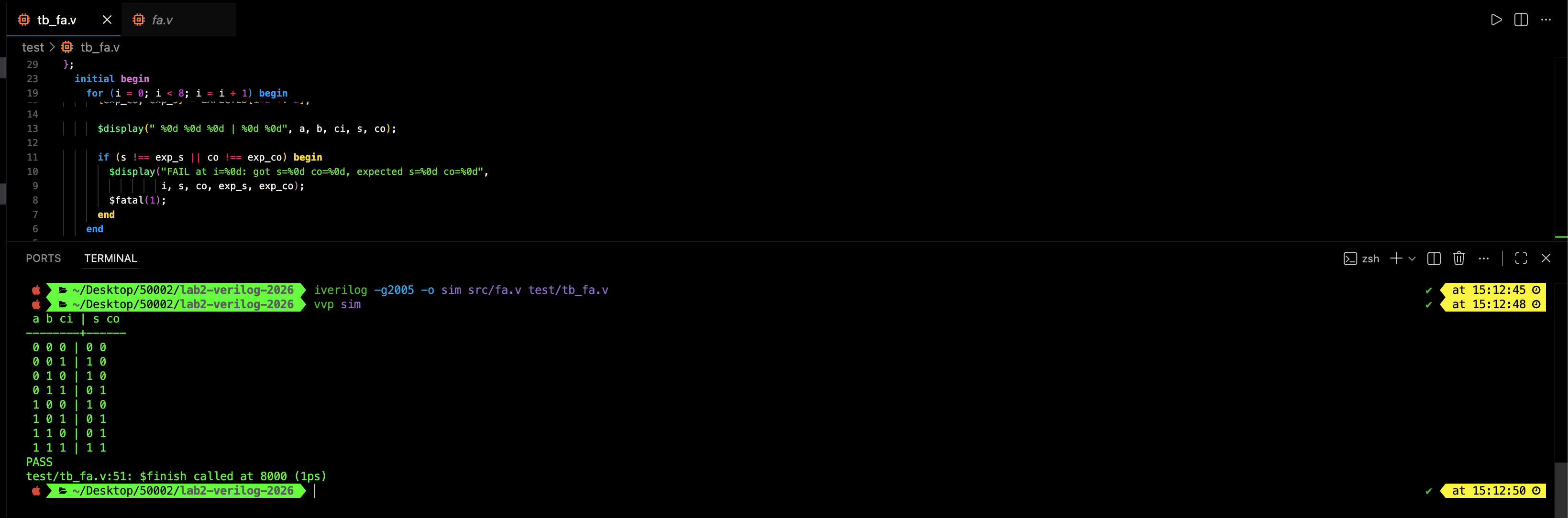
Test: Full Adder
Use this testbench:
// test/tb_fa.v
`timescale 1ns/1ps

module tb_fa;
  reg  a, b, ci;
  wire s, co;

  fa dut (
    .a(a),
    .b(b),
    .ci(ci),
    .s(s),
    .co(co)
  );

// EXPECTED[2*i +: 2] gives {co,s} for input i = {a,b,ci}
localparam [15:0] EXPECTED = {
  2'b11, // i=7  111
  2'b10, // i=6  110
  2'b10, // i=5  101
  2'b01, // i=4  100
  2'b10, // i=3  011
  2'b01, // i=2  010
  2'b01, // i=1  001
  2'b00  // i=0  000
};


  integer i;
  reg exp_s, exp_co;

  initial begin
    $display(" a b ci | s co ");
    $display("--------+------");

    for (i = 0; i < 8; i = i + 1) begin
      {a, b, ci} = i[2:0];
      #1;

      {exp_co, exp_s} = EXPECTED[i*2 +: 2];

      $display(" %0d %0d %0d | %0d %0d", a, b, ci, s, co);

      if (s !== exp_s || co !== exp_co) begin
        $display("FAIL at i=%0d: got s=%0d co=%0d, expected s=%0d co=%0d",
                 i, s, co, exp_s, exp_co);
        $fatal(1);
      end
    end

    $display("PASS");
    $finish;
  end
endmodule
You should see the following success message:
Reg usage in testbench instead of integer
In Verilog testbenches, we use
regfor inputs because signals driven insideinitial/alwaysblocks must be procedurally assignable, andregis the standard 4-state (0/1/x/z), width-selectable type that connects cleanly to module ports (for examplereg [7:0] a;).integeris mainly for loop indices and counters because it is a fixed 32-bit signed variable and is not ideal for representing N-bit wires.
Ripple Carry Adder
We can cascade FA units to form a Ripple-Carry Adder (RCA). The module performs the addition of two one-bit inputs (A and B) incorporating the carry in from the previous stage (Ci). The result appears on the S output and a carry (Co) is generated for the next stage.
A possible schematic for a 4-bit adder is shown below:
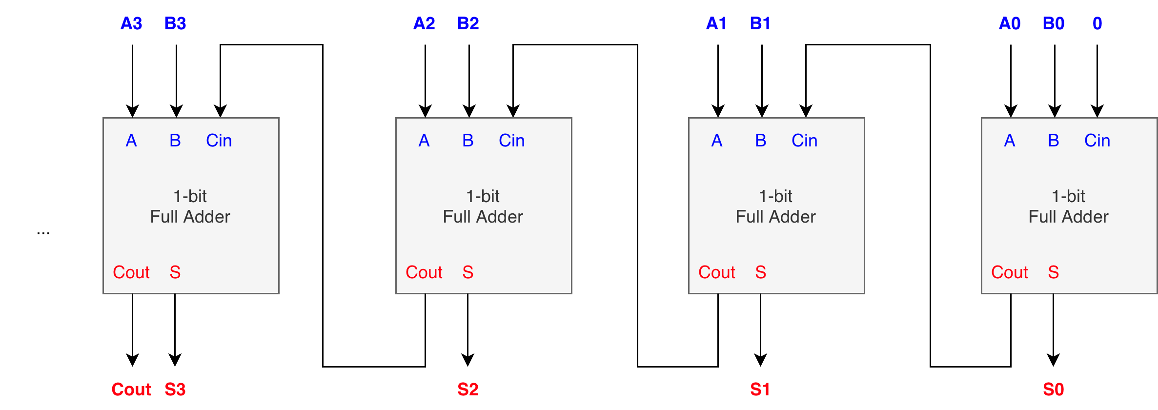
You can pretty much generalise it into N-bit adder. A common value is 32-bit or 64-bit adder. Modern computers typically support 64 bits. Simpler microcontrollers might only support 32 bits.
This module requires a parameter so that we can instantiate it with different values. We also need a for-loop, as well as a bit of knowledge on bit-indexing.
Here’s the starter code:
// src/rca.v
module rca#(
    parameter SIZE = 8 // bit-width
)(
  input  [SIZEN-1:0] a,
  input  [SIZEN-1:0] b,
  input           ci,
  output [SIZEN-1:0] s,
  output          co
)

// your implementation here

endmodule
The
SIZEparameter in the rca module does not make the adder dynamically resizable at runtime. The parameter increases code flexibility, not hardware flexibility.It is a compile-time constant, fixed when the design is built and synthesised. This means the hardware is fully determined before the FPGA is programmed.
The purpose of
SIZEis simply to let you reuse the same module definition for different fixed widths by changing a single value at instantiation time, not to create a variable-width adder during execution.
The following few sections teach you about essential Verilog features that should help you complete the Ripple Carry Adder implementation.
Bit slicing
Bit slicing lets you pick out 1 bit or a group of bits from a bus.
Single-bit indexing
wire [7:0] bus;

wire b0 = bus[0];   // least-significant bit
wire b7 = bus[7];   // most-significant bit
Fixed range (part-select)
wire [15:0] x;

wire [7:0] lo = x[7:0];
wire [7:0] hi = x[15:8];
Indexed part-select (useful for “chunks”)
wire [31:0] x;

wire [7:0] byte0 = x[0  +: 8];  // bits 0..7
wire [7:0] byte2 = x[16 +: 8];  // bits 16..23

wire [7:0] top8  = x[31 -: 8];  // bits 31..24
Common wiring pattern: feed 1 bit into a 1-bit submodule
module bit_cell(input in, output out);
  assign out = in;  // placeholder
endmodule

module top(input [7:0] bus, output y);
  wire t;
  bit_cell u0(.in(bus[3]), .out(t));  // take bit 3
  assign y = t;
endmodule
Parameters
Parameters let you write one module that works for many widths.
Parameter controls port widths
module thing #(
  parameter W = 8
)(
  input  [W-1:0] a,
  input  [W-1:0] b,
  output [W-1:0] y
);
  assign y = a ^ b; // example operation
endmodule
Override a parameter at instantiation
wire [15:0] a16, b16, y16;

thing #(.W(16)) u_thing16 (
  .a(a16),
  .b(b16),
  .y(y16)
);
Derived localparams (compute related sizes once)
module fifo_like #(
  parameter DEPTH = 16
)(
  input  clk
);
  localparam LAST = DEPTH - 1;
  // use LAST internally for bounds, indexing, etc.
endmodule
genvar + generate + for loop
Use generate loops to create repeated hardware instances. Note that this is compile-time expansion, not runtime looping like it is in regular software. This is analogous to repeat in Lucid V2.
This comes very handy to instantiate the fa units SIZE times depending on the size of the rca.
Recall that runtime loops are for simulation behavior when writing testbenches, and not instantiation in a module.
integer i;
initial begin
  for (i = 0; i < 8; i = i + 1) begin
    // good for stimulus, checks, prints
  end
end
You shall use generate loops for repeating module instances like so:
module cell(input in, output out);
  assign out = in; // placeholder
endmodule

module array_of_cells #(
  parameter N = 8
)(
  input  [N-1:0] in_bus,
  output [N-1:0] out_bus
);
  genvar i;

  generate
    for (i = 0; i < N; i = i + 1) begin : gen_cells
      cell u_cell (
        .in (in_bus[i]),
        .out(out_bus[i])
      );
    end
  endgenerate
endmodule
The following explains the syntax surrounding generate statement:
genvar iis a special variable used only for generation. It is not a runtime variable.begin : gen_cellsis important because it creates a named scope for each generated copy, giving predictable names.- Even though the instance name
u_cellis written once, each generated copy is still unique because it lives under a different scope.
As a result, your tool creates an array of instances with hierarchical names:
gen_cells[0].u_cellgen_cells[1].u_cellgen_cells[2].u_cell- …
Therefore in Verilog/SystemVerilog you index the module instances themselves (for example gen_cells[3].u_cell) instead of indexing a port like a vectorised module in Lucid.
genvaris used only ingenerateloops. The named block (begin : gen_cells) creates predictable instance names likegen_cells[0].u_cell.A generate loop physically replicates hardware structure N times.
Test: Ripple Carry Adder
This testbench instantiates two DUTs (4-bit and 8-bit RCAs) and reuses the same check_one task. expected is computed using normal int addition, then compared against {co, s}. Inputs are masked to N bits so random 32-bit values still behave like N bit vectors.
// test/tb_rca.v
`timescale 1ns/1ps

module tb_rca;

  // ----------------------------
  // DUTs: 4-bit and 8-bit RCAs
  // ----------------------------
  reg  [3:0] a4, b4;  reg  ci4;  wire [3:0] s4;  wire co4;
  reg  [7:0] a8, b8;  reg  ci8;  wire [7:0] s8;  wire co8;

  rca #(.SIZE(4)) dut4 (.a(a4), .b(b4), .ci(ci4), .s(s4), .co(co4));
  rca #(.SIZE(8)) dut8 (.a(a8), .b(b8), .ci(ci8), .s(s8), .co(co8));

  // ----------------------------
  // Test vectors (truncated)
  // Pack each vector as {ci, a, b}
  // ----------------------------
  localparam integer TV4_N = 10;
  localparam integer TV8_N = 10;

  reg [8:0]  tv4 [0:TV4_N-1];   // {ci[8], a[7:4], b[3:0]}
  reg [16:0] tv8 [0:TV8_N-1];   // {ci[16], a[15:8], b[7:0]}

  integer i;
  reg [4:0] exp4;               // {co, s} for 4-bit
  reg [8:0] exp8;               // {co, s} for 8-bit

  initial begin
    // TEST VALUES
    // -----------
    // 4-bit vectors
    // -----------
    tv4[0] = {1'b0, 4'h0, 4'h0};
    tv4[1] = {1'b0, 4'h0, 4'h1};
    tv4[2] = {1'b0, 4'h1, 4'h1};
    tv4[3] = {1'b0, 4'h3, 4'h5};
    tv4[4] = {1'b0, 4'hF, 4'h0};
    tv4[5] = {1'b0, 4'hF, 4'h1}; // overflow
    tv4[6] = {1'b0, 4'hF, 4'hF}; // overflow
    tv4[7] = {1'b1, 4'h0, 4'h0}; // carry-in only
    tv4[8] = {1'b1, 4'h7, 4'h8}; // with carry-in
    tv4[9] = {1'b1, 4'hF, 4'hF}; // max + max + carry-in

    // -----------
    // 8-bit vectors
    // -----------
    tv8[0] = {1'b0, 8'h00, 8'h00};
    tv8[1] = {1'b0, 8'h00, 8'h01};
    tv8[2] = {1'b0, 8'h01, 8'h01};
    tv8[3] = {1'b0, 8'h7F, 8'h01};
    tv8[4] = {1'b0, 8'hFF, 8'h01}; // overflow
    tv8[5] = {1'b0, 8'hFF, 8'hFF}; // overflow
    tv8[6] = {1'b0, 8'h55, 8'hAA}; // pattern
    tv8[7] = {1'b0, 8'h80, 8'h80}; // overflow
    tv8[8] = {1'b1, 8'h00, 8'h00}; // carry-in only
    tv8[9] = {1'b1, 8'hFF, 8'hFF}; // max + max + carry-in

    // ============================
    // Run 4-bit tests
    // ============================
    $display("=== Testing RCA N=4 ===");
    for (i = 0; i < TV4_N; i = i + 1) begin
      ci4 = tv4[i][8];
      a4  = tv4[i][7:4];
      b4  = tv4[i][3:0];
      #1;

      exp4 = {1'b0, a4} + {1'b0, b4} + ci4;

      if ({co4, s4} !== exp4) begin
        $display("FAIL N=4 vec=%0d a=%0h b=%0h ci=%0d | got co=%0d s=%0h expected co=%0d s=%0h",
                 i, a4, b4, ci4, co4, s4, exp4[4], exp4[3:0]);
        $fatal(1);
      end
    end
    $display("PASS N=4");

    // ============================
    // Run 8-bit tests
    // ============================
    $display("=== Testing RCA N=8 ===");
    for (i = 0; i < TV8_N; i = i + 1) begin
      ci8 = tv8[i][16];
      a8  = tv8[i][15:8];
      b8  = tv8[i][7:0];
      #1;

      exp8 = {1'b0, a8} + {1'b0, b8} + ci8;

      if ({co8, s8} !== exp8) begin
        $display("FAIL N=8 vec=%0d a=%0h b=%0h ci=%0d | got co=%0d s=%0h expected co=%0d s=%0h",
                 i, a8, b8, ci8, co8, s8, exp8[8], exp8[7:0]);
        $fatal(1);
      end
    end
    $display("PASS N=8");

    $display("ALL PASS");
    $finish;
  end

endmodule
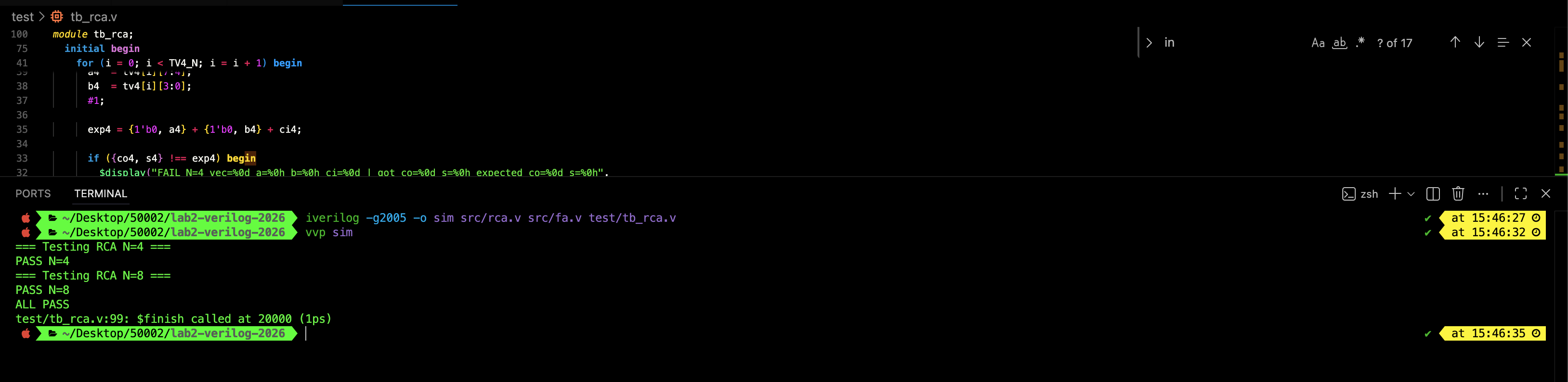
You shall compile with the command to include fa.v too:
iverilog -g2005 -o sim src/rca.v src/fa.v test/tb_rca.v
vvp sim
If your rca is correctly implemented, you should see the following message;
“2D arrays” in Verilog testbenches (memories) vs parameter arrays
In Verilog-2005, you can write things that look like 2D arrays using the memory syntax. This is very common in testbenches for storing test vectors:
reg [8:0] tv4 [0:9]; // 10 entries, each entry is 9 bits
This is NOT a true “2D bus” port. It is a memory (an array of vectors). You typically fill it inside an initial block:
initial begin
  tv4[0] = 9'h000;
  tv4[1] = 9'h123;
  ...
end
As mentioned before, Verilog-2005 generally does not support unpacked arrays of parameters, so this often fails. You should use SystemVerilog instead.
localparam [8:0] TV4 [0:9] = ...; // SystemVerilog-style, usually not Verilog-2005
In short, use reg [W-1:0] mem [0:DEPTH-1] for testbench lookup tables (supported in Verilog-2005). If you need a constant table in Verilog-2005, use a packed vector and slice it, or use a function with a case statement.
Pattern 1: packed constant vector + slicing
localparam [9*10-1:0] TV4_PACKED = {
  9'h..., 9'h..., 9'h... // 10 entries
};

wire [8:0] vec = TV4_PACKED[i*9 +: 9];
Pattern 2: function + case
function [8:0] tv4_vec;
  input integer idx;
  begin
    case (idx)
      0: tv4_vec = 9'h...;
      1: tv4_vec = 9'h...;
      default: tv4_vec = 9'h000;
    endcase
  end
endfunction
A Neater Testbench
We can create rom modules to hold the test values and let the test bench extract from it.
Here’s a simple code for two small “ROM” modules (really just a case table) that take an index and output {ci, a, b, expected}. Then the testbench just loops idx = 0..15.
// test/tv_rom_rca.v
// ----------------------------------------
// Test-vector ROM for 4-bit RCA
// idx: 0..15
// outputs: ci, a, b, expected {co,s}
// ----------------------------------------
module tv_rom4(
  input  [3:0] idx,
  output reg        ci,
  output reg [3:0]  a,
  output reg [3:0]  b,
  output reg [4:0]  exp   // {co, s[3:0]}
);
  always @* begin
    // defaults
    ci  = 1'b0;
    a   = 4'h0;
    b   = 4'h0;
    exp = 5'h00;

    case (idx)
      4'd0:  begin ci=0; a=4'h0; b=4'h0; exp=5'h00; end // 0x0 + 0x0 + 0 = 0x00
      4'd1:  begin ci=0; a=4'h0; b=4'h1; exp=5'h01; end // 0x0 + 0x1 + 0 = 0x01
      4'd2:  begin ci=0; a=4'h1; b=4'h1; exp=5'h02; end // 0x1 + 0x1 + 0 = 0x02
      4'd3:  begin ci=0; a=4'h3; b=4'h5; exp=5'h08; end // 0x3 + 0x5 + 0 = 0x08
      4'd4:  begin ci=0; a=4'h7; b=4'h8; exp=5'h0F; end // 0x7 + 0x8 + 0 = 0x0F
      4'd5:  begin ci=0; a=4'hF; b=4'h0; exp=5'h0F; end // 0xF + 0x0 + 0 = 0x0F
      4'd6:  begin ci=0; a=4'hF; b=4'h1; exp=5'h10; end // 0xF + 0x1 + 0 = 0x10 (carry)
      4'd7:  begin ci=0; a=4'hF; b=4'hF; exp=5'h1E; end // 0xF + 0xF + 0 = 0x1E

      4'd8:  begin ci=1; a=4'h0; b=4'h0; exp=5'h01; end // 0x0 + 0x0 + 1 = 0x01
      4'd9:  begin ci=1; a=4'h0; b=4'hF; exp=5'h10; end // 0x0 + 0xF + 1 = 0x10
      4'd10: begin ci=1; a=4'h7; b=4'h7; exp=5'h0F; end // 0x7 + 0x7 + 1 = 0x0F
      4'd11: begin ci=1; a=4'h8; b=4'h8; exp=5'h11; end // 0x8 + 0x8 + 1 = 0x11 (carry)
      4'd12: begin ci=1; a=4'hA; b=4'h5; exp=5'h10; end // 0xA + 0x5 + 1 = 0x10
      4'd13: begin ci=1; a=4'hC; b=4'h3; exp=5'h10; end // 0xC + 0x3 + 1 = 0x10
      4'd14: begin ci=1; a=4'hF; b=4'h0; exp=5'h10; end // 0xF + 0x0 + 1 = 0x10
      4'd15: begin ci=1; a=4'hF; b=4'hF; exp=5'h1F; end // 0xF + 0xF + 1 = 0x1F
    endcase
  end
endmodule


// ----------------------------------------
// Test-vector ROM for 8-bit RCA
// idx: 0..15
// outputs: ci, a, b, expected {co,s}
// ----------------------------------------
module tv_rom8(
  input  [3:0] idx,
  output reg        ci,
  output reg [7:0]  a,
  output reg [7:0]  b,
  output reg [8:0]  exp   // {co, s[7:0]}
);
  always @* begin
    ci  = 1'b0;
    a   = 8'h00;
    b   = 8'h00;
    exp = 9'h000;

    case (idx)
      4'd0:  begin ci=0; a=8'h00; b=8'h00; exp=9'h000; end // 0x00 + 0x00 + 0 = 0x000
      4'd1:  begin ci=0; a=8'h00; b=8'h01; exp=9'h001; end // 0x00 + 0x01 + 0 = 0x001
      4'd2:  begin ci=0; a=8'h01; b=8'h01; exp=9'h002; end // 0x01 + 0x01 + 0 = 0x002
      4'd3:  begin ci=0; a=8'h0F; b=8'h01; exp=9'h010; end // 0x0F + 0x01 + 0 = 0x010
      4'd4:  begin ci=0; a=8'h7F; b=8'h01; exp=9'h080; end // 0x7F + 0x01 + 0 = 0x080
      4'd5:  begin ci=0; a=8'h80; b=8'h80; exp=9'h100; end // 0x80 + 0x80 + 0 = 0x100 (carry)
      4'd6:  begin ci=0; a=8'hFF; b=8'h01; exp=9'h100; end // 0xFF + 0x01 + 0 = 0x100 (carry)
      4'd7:  begin ci=0; a=8'hFF; b=8'hFF; exp=9'h1FE; end // 0xFF + 0xFF + 0 = 0x1FE

      4'd8:  begin ci=0; a=8'h55; b=8'hAA; exp=9'h0FF; end // 0x55 + 0xAA + 0 = 0x0FF
      4'd9:  begin ci=0; a=8'h12; b=8'h34; exp=9'h046; end // 0x12 + 0x34 + 0 = 0x046
      4'd10: begin ci=0; a=8'hFE; b=8'h01; exp=9'h0FF; end // 0xFE + 0x01 + 0 = 0x0FF
      4'd11: begin ci=0; a=8'hF0; b=8'h10; exp=9'h100; end // 0xF0 + 0x10 + 0 = 0x100 (carry)

      4'd12: begin ci=1; a=8'h00; b=8'h00; exp=9'h001; end // 0x00 + 0x00 + 1 = 0x001
      4'd13: begin ci=1; a=8'h00; b=8'hFF; exp=9'h100; end // 0x00 + 0xFF + 1 = 0x100 (carry)
      4'd14: begin ci=1; a=8'h7F; b=8'h80; exp=9'h100; end // 0x7F + 0x80 + 1 = 0x100 (carry)
      4'd15: begin ci=1; a=8'hFF; b=8'hFF; exp=9'h1FF; end // 0xFF + 0xFF + 1 = 0x1FF
    endcase
  end
endmodule
We use case in Verilog for the rom module above. Read below for more information about it.
And the testbench now just extract the test case:
// test/tb_rca_rom.v
`timescale 1ns/1ps

module tb_rca_rom;

  // DUTs
  reg  [3:0] a4, b4;  reg  ci4;  wire [3:0] s4;  wire co4;
  reg  [7:0] a8, b8;  reg  ci8;  wire [7:0] s8;  wire co8;

  rca #(.SIZE(4)) dut4 (.a(a4), .b(b4), .ci(ci4), .s(s4), .co(co4));
  rca #(.SIZE(8)) dut8 (.a(a8), .b(b8), .ci(ci8), .s(s8), .co(co8));

  // ROM outputs
  reg  [3:0] idx;
  wire       rom_ci4; wire [3:0] rom_a4, rom_b4; wire [4:0] rom_exp4;
  wire       rom_ci8; wire [7:0] rom_a8, rom_b8; wire [8:0] rom_exp8;

  tv_rom4 rom4(.idx(idx), .ci(rom_ci4), .a(rom_a4), .b(rom_b4), .exp(rom_exp4));
  tv_rom8 rom8(.idx(idx), .ci(rom_ci8), .a(rom_a8), .b(rom_b8), .exp(rom_exp8));

  integer i;
  reg [4:0] exp4_arith;
  reg [8:0] exp8_arith;

  initial begin
    // ----------------
    // 4-bit tests
    // ----------------
    $display("=== RCA N=4 (ROM-driven) ===");
    for (i = 0; i < 16; i = i + 1) begin
      idx = i[3:0];
      #1; // allow ROM outputs to settle

      a4  = rom_a4;
      b4  = rom_b4;
      ci4 = rom_ci4;
      #1; // allow DUT outputs to settle

      // Optional: arithmetic cross-check (should match ROM)
      exp4_arith = {1'b0, a4} + {1'b0, b4} + ci4;

      if (rom_exp4 !== exp4_arith) begin
        $display("ROM MISMATCH N=4 idx=%0d rom_exp=%0h arith=%0h", i, rom_exp4, exp4_arith);
        $fatal(1);
      end

      if ({co4, s4} !== rom_exp4) begin
        $display("FAIL N=4 idx=%0d a=%0h b=%0h ci=%0d | got=%0h expected=%0h",
                 i, a4, b4, ci4, {co4, s4}, rom_exp4);
        $fatal(1);
      end
    end
    $display("PASS N=4");

    // ----------------
    // 8-bit tests
    // ----------------
    $display("=== RCA N=8 (ROM-driven) ===");
    for (i = 0; i < 16; i = i + 1) begin
      idx = i[3:0];
      #1;

      a8  = rom_a8;
      b8  = rom_b8;
      ci8 = rom_ci8;
      #1;

      exp8_arith = {1'b0, a8} + {1'b0, b8} + ci8;

      if (rom_exp8 !== exp8_arith) begin
        $display("ROM MISMATCH N=8 idx=%0d rom_exp=%0h arith=%0h", i, rom_exp8, exp8_arith);
        $fatal(1);
      end

      if ({co8, s8} !== rom_exp8) begin
        $display("FAIL N=8 idx=%0d a=%0h b=%0h ci=%0d | got=%0h expected=%0h",
                 i, a8, b8, ci8, {co8, s8}, rom_exp8);
        $fatal(1);
      end
    end
    $display("PASS N=8");

    $display("ALL PASS");
    $finish;
  end

endmodule
A ROM-style case table is a clean way to keep test vectors “constant” in Verilog-2005 without relying on unsupported localparam arrays. It also separates the data (test cases) from the loop/check logic, making failures easier to reproduce and the vectors easier for users to edit.
2-to-1 MUX and 4-to-2 MUX
Here’s the interface for you to get started:
// src/MUX2to1.v
// 2-to-1 MUX (1-bit)
module MUX2to1 (
  input  wire data0,
  input  wire data1,
  input  wire s,
  output wire y
);

  // your implementation here

endmodule
// src/MUX4to2.v
// 4-to-1 MUX (1-bit), selected by 2-bit s
module MUX4to1 (
  input  wire data0,
  input  wire data1,
  input  wire data2,
  input  wire data3,
  input  wire [1:0] s,
  output wire y
);

    // your implementation here
    // you are encouraged to utilise MUX2to1 here

endmodule
To implement these effectively, you would need to know a little bit about control flow (if, case) and ternary operator.
Conditionals in Verilog
Verilog gives you two common styles for conditional logic: continuous assignments (often with the ternary operator) and procedural blocks (always @*) using if/else or case. Both can describe the same combinational hardware. The choice is mostly about clarity and scalability.
Ternary operator (continuous assignment)
This is best for small, simple selections. Recommended to be used to implement the MUXes.
assign y = sel ? d1 : d0; // 2-to-1 MUX
You can chain ternaries for bigger MUXes like so, but it gets hard to read.
assign y = (s == 2'b00) ? d0 :
           (s == 2'b01) ? d1 :
           (s == 2'b10) ? d2 :
                          d3;
always @* with if/else (procedural combinational)
Use this when logic is more complex or you prefer step-by-step readability.
reg y;

always @* begin
  if (sel) y = d1;
  else     y = d0;
end
In this style, outputs assigned inside always must be declared reg (even though it is still combinational logic).
always @* with case (procedural combinational)
This is best when you have many discrete choices, like MUXes with larger select signals.
reg y;

always @* begin
  case (s)
    2'b00: y = d0;
    2'b01: y = d1;
    2'b10: y = d2;
    2'b11: y = d3;
  endcase
end
Avoid accidental latches by assigning a default
In combinational always @* blocks, make sure every output gets a value on all paths. As mentioned before, the common pattern is to set a default first:
always @* begin
  y = d0;        // default
  if (sel) y = d1;
end
or include a default: in case:
always @* begin
  case (s)
    2'b00: y = d0;
    2'b01: y = d1;
    2'b10: y = d2;
    default: y = d3;
  endcase
end
With these 3 choices, you are advised to:
- Use
assign+ ternary for short MUX-style expressions.- Use
always @*+if/casewhen the selection has many cases or the code reads clearer.When using
always @*, always provide a default assignment (or full coverage) to keep the logic purely combinational.
Test: Multiplexers
This testbench contains the def of two modules at once, one to test each MUX. Then there’s a top level testbench that runs both in sequence.
// test/tb_MUX.v
`timescale 1ns/1ps


// --------------------
// TB 1: MUX2to1
// Runs only after start=1, then raises done=1
// --------------------
module tb_MUX2to1 (
  input  wire start,
  output reg  done
);
  reg  data0, data1, s;
  wire y;

  MUX2to1 dut (.data0(data0), .data1(data1), .s(s), .y(y));

  integer i;
  reg exp;

  initial begin
    done = 1'b0;
    wait (start == 1'b1);

    $display("=== tb_MUX2to1 ===");
    $display("d0 d1 s | y");

    for (i = 0; i < 8; i = i + 1) begin
      {data0, data1, s} = i[2:0];
      #1;

      exp = s ? data1 : data0;

      $display("%0d  %0d  %0d | %0d", data0, data1, s, y);

      if (y !== exp) begin
        $display("FAIL i=%0d: d0=%0d d1=%0d s=%0d got y=%0d expected y=%0d",
                 i, data0, data1, s, y, exp);
        $fatal(1);
      end
    end

    $display("PASS");
    done = 1'b1;
  end
endmodule

// --------------------
// TB 2: MUX4to1
// Runs only after start=1, then raises done=1
// --------------------
module tb_MUX4to1 (
  input  wire start,
  output reg  done
);
  reg  data0, data1, data2, data3;
  reg  [1:0] s;
  wire y;

  MUX4to1 dut (.data0(data0), .data1(data1), .data2(data2), .data3(data3), .s(s), .y(y));

  integer i;
  reg exp;

  initial begin
    done = 1'b0;
    wait (start == 1'b1);

    $display("=== tb_MUX4to1 ===");
    $display("d0 d1 d2 d3 s | y");

    for (i = 0; i < 64; i = i + 1) begin
      {data0, data1, data2, data3, s} = i[5:0];
      #1;

      case (s)
        2'b00: exp = data0;
        2'b01: exp = data1;
        2'b10: exp = data2;
        2'b11: exp = data3;
      endcase

      $display("%0d  %0d  %0d  %0d  %02b | %0d", data0, data1, data2, data3, s, y);

      if (y !== exp) begin
        $display("FAIL i=%0d: d0=%0d d1=%0d d2=%0d d3=%0d s=%02b got y=%0d expected y=%0d",
                 i, data0, data1, data2, data3, s, y, exp);
        $fatal(1);
      end
    end

    $display("PASS");
    done = 1'b1;
  end
endmodule

// --------------------
// Top-level sequencer
// Starts TB1, waits, then starts TB2
// --------------------
module tb_all;
  reg start1, start2;
  wire done1, done2;

  tb_MUX2to1 t1(.start(start1), .done(done1));
  tb_MUX4to1 t2(.start(start2), .done(done2));

  initial begin
    start1 = 1'b0;
    start2 = 1'b0;

    #1; start1 = 1'b1;
    wait (done1 == 1'b1);

    $display("");
    #1; start2 = 1'b1;
    wait (done2 == 1'b1);

    $display("");
    $display("ALL PASS");
    $finish;
  end
endmodule
Don’t forget to include all modules when compiling and running:
iverilog -g2005 -o sim src/MUX2to1.v src/MUX4to2.v test/tb_MUX.v `
If all goes well, this is what you should see:
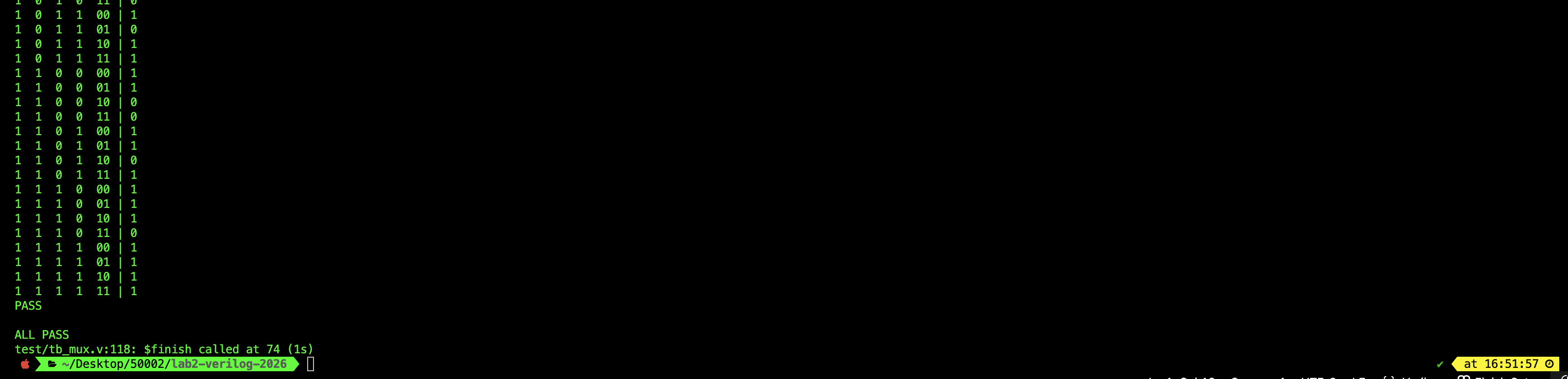
1-to-2 and 2-to-4 Decoder
Here’s the starter code:
// src/decoder1to2.v
// 1-to-2 decoder with enable (v)
// if v=0: y0=y1=0
// if v=1: y0=~a, y1=a
module decoder1to2 (
  input  wire v,
  input  wire a,
  output wire y0,
  output wire y1
);

  // your code here

endmodule
// src/decoder2to4.v
// 2-to-4 decoder with enable (v)
// if v=0: all outputs 0
// if v=1: exactly one output high based on a[1:0]
module decoder2to4 (
  input  wire v,
  input  wire [1:0] a,
  output wire y0,
  output wire y1,
  output wire y2,
  output wire y3
);
    // your code here
    // you are encouraged to utilise decoder1to2 here
endmodule
The implementation should be straightforward, with simple assign.
Test: Decoder
// test/tb_decoder.v
// --------------------
// TB 1: decoder1to2
// Runs only after start=1, then raises done=1
// --------------------
module tb_decoder1to2 (
  input  wire start,
  output reg  done
);
  reg  v, a;
  wire y0, y1;

  decoder1to2 dut (.v(v), .a(a), .y0(y0), .y1(y1));

  integer i;
  reg exp_y0, exp_y1;

  initial begin
    done = 1'b0;
    wait (start == 1'b1);

    $display("=== tb_decoder1to2 ===");
    $display("v a | y0 y1");

    for (i = 0; i < 4; i = i + 1) begin
      {v, a} = i[1:0];
      #1;

      exp_y0 = v & ~a;
      exp_y1 = v &  a;

      $display("%0d %0d |  %0d  %0d", v, a, y0, y1);

      if (y0 !== exp_y0 || y1 !== exp_y1) begin
        $display("FAIL i=%0d: v=%0d a=%0d got y0=%0d y1=%0d expected y0=%0d y1=%0d",
                 i, v, a, y0, y1, exp_y0, exp_y1);
        $fatal(1);
      end
    end

    $display("PASS");
    done = 1'b1;
  end
endmodule

// --------------------
// TB 2: decoder2to4
// Runs only after start=1, then raises done=1
// --------------------
module tb_decoder2to4 (
  input  wire start,
  output reg  done
);
  reg  v;
  reg  [1:0] a;
  wire y0, y1, y2, y3;

  decoder2to4 dut (.v(v), .a(a), .y0(y0), .y1(y1), .y2(y2), .y3(y3));

  integer i;
  reg exp_y0, exp_y1, exp_y2, exp_y3;

  initial begin
    done = 1'b0;
    wait (start == 1'b1);

    $display("=== tb_decoder2to4 ===");
    $display("v a1 a0 | y0 y1 y2 y3");

    for (i = 0; i < 8; i = i + 1) begin
      {v, a} = i[2:0];
      #1;

      exp_y0 = v & ~a[1] & ~a[0];
      exp_y1 = v & ~a[1] &  a[0];
      exp_y2 = v &  a[1] & ~a[0];
      exp_y3 = v &  a[1] &  a[0];

      $display("%0d  %0d  %0d  |  %0d  %0d  %0d  %0d",
               v, a[1], a[0], y0, y1, y2, y3);

      if (y0 !== exp_y0 || y1 !== exp_y1 || y2 !== exp_y2 || y3 !== exp_y3) begin
        $display("FAIL i=%0d: v=%0d a=%02b got y0..y3=%0d%0d%0d%0d expected y0..y3=%0d%0d%0d%0d",
                 i, v, a, y0, y1, y2, y3, exp_y0, exp_y1, exp_y2, exp_y3);
        $fatal(1);
      end
    end

    $display("PASS");
    done = 1'b1;
  end
endmodule

// --------------------
// Top-level sequencer
// Starts TB1, waits, then starts TB2
// --------------------
module tb_all;
  reg start1, start2;
  wire done1, done2;

  tb_decoder1to2 t1(.start(start1), .done(done1));
  tb_decoder2to4 t2(.start(start2), .done(done2));

  initial begin
    start1 = 1'b0;
    start2 = 1'b0;

    #1; start1 = 1'b1;
    wait (done1 == 1'b1);

    $display("");
    #1; start2 = 1'b1;
    wait (done2 == 1'b1);

    $display("");
    $display("ALL PASS");
    $finish;
  end
endmodule
If you implemented your decoders properly, this is what you should see:
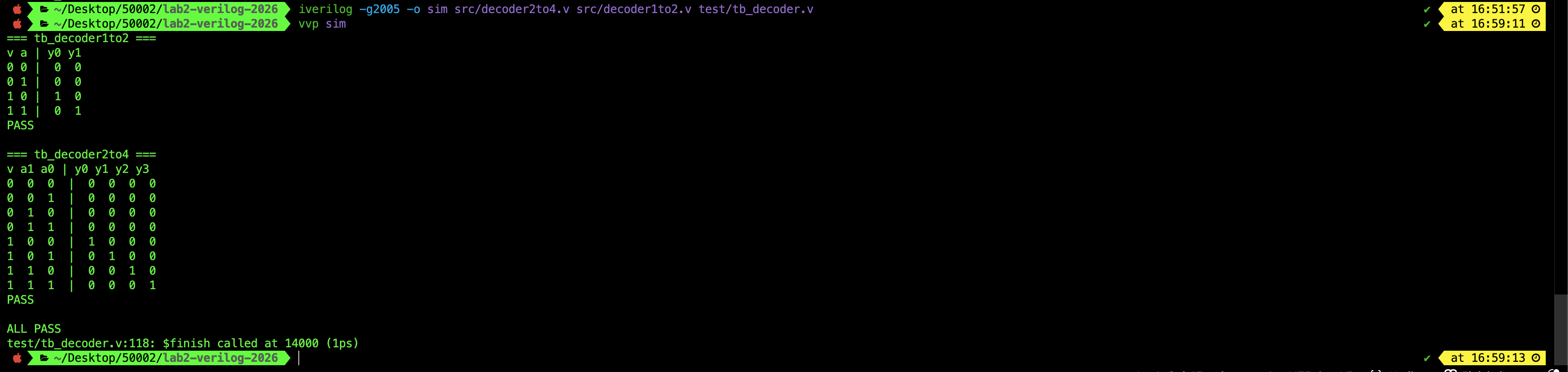
First Principles Before Generalisation
When learning HDL, resist the urge to over-engineer, over-refactor, or over-modularise immediately.
If you are new, you should first write the basic circuits out explicitly, even if it feels repetitive or boring. Mundane repetition is acceptable at this stage, because it forces you to see exactly which signals connect where.
Do not rush to create a fully generic “N-to-2^n decoder” or a super-parameterised Mux yet.
- Get the concrete 1-to-2 and 2-to-4 versions correct and readable first.
- Only then is it meaningful to generalise.
- Sometimes it is not even important to generalise because for instance, you’re not going to USE that many variations of MUX/decoder in your project in the first place. So who are you making it for?
- If it is for learning and you have free time on hand, great. Go ahead.
- But if it introduces bugs and frustration, that means your knowledge is not adequate yet. Stick to the basics. They always work with minimal errors.
Similarly, using AI tools to generate clever abstractions before you understand the syntax and semantics yourself is counterproductive. In 50002, the goal is not rapid prototyping. The goal is to internalise the basic building blocks of digital logic.
Module Array Indexing in Verilog
In Verilog/SystemVerilog, you do not have “vectorised ports” on a single module instance the way Lucid does. Instead, you create multiple module instances (typically with a generate loop), and the indexing applies to the instance array, not the port.
Example: generate an array of instances
genvar i;
generate
  for (i = 0; i < N; i = i + 1) begin : cells
    my_cell u (
      .in (in_bus[i]),
      .out(out_bus[i])
    );
  end
endgenerate
How you reference signals
- In simulation/debug, you refer to the instance by its generated name and index:
cells[0].ucells[3].u
- And then you access the port/net inside that instance through the hierarchical path (tool-dependent syntax), conceptually:
cells[3].u.out
In Verilog, the “array-ness” comes from having many instances, each with its own scalar ports. You index the instances created by the generate block, rather than indexing a port on one vectorised module.
Do NOT use instance.output_port (hierarchical references) in Verilog
All of the Verilog examples mentioned above always uses intermediary variable like wire or reg when referencing the output port of any module instances if you use it within another module. This is unlike Lucid where you can casually use stuffs like this:
  rca adder
  sig x
  always {
    x = ~|adder.s // hierarchical references
    // other code
  }
In synthesizable RTL (Register Transfer Language, which is a particular way of using HDL like verilog), you should treat module ports like “pins on a chip”:
- Connect them to named signals,
- Then use those signals in the rest of your design.
RTL
HDL code written to model hardware as registers + combinational logic between them, in a synthesizable, synchronous style.
For example, writing adder.s is a hierarchical reference (reaching into an instance). Some simulators allow it, but many synthesis tools and linters reject it, and it makes your design fragile because renaming the instance or restructuring modules can silently break code (fragile).
rca adder (
  .a(a),
  .b(b),
  .s()          // left unconnected
);

// Later:
assign y = adder.s; // hierarchical reference (do NOT do this)
The above might work in some simulators but you should not treat it as valid for real RTL design because it is fragile and therefore NOT a good design.
Instead, this is a good practice:
wire [31:0] s;

rca adder (
  .a(a),
  .b(b),
  .s(s)          // connected to wire s
);

assign y = s;
Sometimes instance.port is acceptable but only in testbenches/debug (peeking at internal signals) or in tool-specific assertion flows. For this course, always connect ports to explicit signals and use those signals instead.
Summary
This lab mirrors the Lucid Lab 2 flow in plain Verilog: implement a 1-bit full adder from Boolean logic, cascade it into a parameterised ripple-carry adder using genvar + generate, then build MUXes and decoders as core combinational blocks with small, readable modules plus testbenches.
Key takeaways:
- Build from first principles: Boolean expressions and small modules (avoid + for the 1-bit adder).
- Use parameters for fixed compile-time widths, and
generateloops to replicate hardware structure. - Encourages composition: build MUX4to1 from MUX2to1, and decoder2to4 from decoder1to2.
- Verify with testbenches; use ROM-style case tables when you want “constant” vectors under Verilog-2005.
Checkoff
There’s no checkoff for this Verilog version. Simply complete the tasks on your own. You still need to do checkoffs with your TAs using Lucid in class.