 50.002 CS
- Objectives
- Submission
- Starter Code
- Related Class Materials
- Control Sequencing with Finite State Machines
- Datapath
- FSM controller
- Feedback Signals
- Control Signals
- Implementing an FSM in HDL
- Processing Button Presses
- Building the Automated Register Adder Tester
- Checkoff
- Summary
- Appendix
50.002 Computation Structures
Information Systems Technology and Design
Singapore University of Technology and Design
Lab 4: Control Sequencing
Objectives
By the end of this lab, we should be able to:
- Explain how an FSM acts as a controller that issues sequencing decisions to a datapath.
- Separate a hardware design cleanly into datapath (storage, operations, comparison) and controller (state transitions and control signals).
- Describe why a self-checking tester requires registered inputs, pipelined expected outputs, and synchronised control.
- Implement a multi-state FSM in Lucid with correct state encoding, output logic and next-state logic.
- Use a
slow clock,edge detector, andbutton conditionerto control transitions cleanly on hardware. - Build an automated tester that increments test cases, samples inputs over multiple cycles, compares pipelined outputs, halts on mismatch, and restarts reliably via a button press.
Submission
Complete the Lab 4 checkoff (2%) with your Cohort TA before the end of next Friday, 6PM (unless otherwise stated). You should demonstrate the required task under the Checkoff section below. Unlike the previous labs, from this lab onwards, the checkoff is assessed AS A GROUP as it requires the FPGA hardware.
Complete questionnaire on eDimension as well (2%).
Starter Code
There’s no starter code for this lab. You simply need to have Alchitry Labs V2 installed. You will also need Vivado for this lab. Refer to the installation guideline if you have not read them.
Related Class Materials
The lecture notes on FSM and Turing Machine are closely related to this lab.
| Lecture notes topic | Lab 4 part |
|---|---|
| FSM formal model: states, transitions, Moore vs Mealy, state registers, next-state logic | Implementing the tester FSM (IDLE, INIT, WAIT_1, WAIT_2, CHECK, HALT) with a state DFF and case-based transitions |
| FSM as “control logic” separate from datapath | Using control signals (index_load_zero, index_inc, sample_enable, running) to drive datapath behaviour each slow-clock tick |
| Deriving control outputs from state | Writing deterministic control actions under each state bubble: initialise, feed, wait, compare, halt |
| Recognising the need for timing boundaries | Understanding why sampling (a, b) and capturing s require two distinct WAIT cycles, not one |
| FSM responsiveness and clocking discipline: synchronous inputs, metastability, debouncing | Using button_conditioner and edge_detector so button presses become single clean events; ensuring transitions wait for slow-clock edges |
Transition conditions from datapath signals (equal, last_index, error flags) |
Wiring comparator output and index-boundary logic into the FSM to decide when to increment or halt |
| Turing Machine conceptual link: sequencing through symbolic steps with a simple controller | Mapping “control of a procedure” to the hardware tester sequence: initialise » feed » delay » check » branch (continue or halt) |
| Finite programs encoded as state graphs | Designing the 7-state “hardware program” that steps through test vectors and terminates on mismatch |
| Modular design principles: keep computation inside datapath, keep sequencing in controller | Datapath contains the RCA, pipeline registers, ROM arrays, comparator; the FSM never performs arithmetic, only drives control wires |
| Hazards from asynchronous events | Explaining why raw button signals break the FSM and why conditioning + edge detection is required |
Control Sequencing with Finite State Machines
Up to Lab 3, most of the circuits you built were data driven:
- You wired an adder to some inputs
- You added registers so values update on each clock
- You used a testbench to supply the inputs and read the outputs
In this lab, you will add a small controller whose job is to decide: “What should the circuit do on this clock tick?”
This kind of controller is none other than a Finite State Machine (FSM).
Motivation
Recap: digital systems that do more than “pure combinational logic” usually have two different kinds of logic living together:
- Sequencing: deciding what happens first, next, and last.
- Computation and storage: holding values in registers and running arithmetic or comparisons on them.
A clean RTL structure (description of hardware in HDL like Verilog or Lucid) separates these two roles.
The controller is none other than an FSM. It decides the sequence of steps. It outputs control signals such as ld_x, clr_x, sel_x, we, done, and so on.
The datapath contains the registers and the combinational logic between them. It performs the computation when the controller tells it to. It also produces status signals (flags) such as zero, lt, eq, carry, busy, ready, which feed back into the controller so the FSM can branch or wait.
This separation matters in the code because it matches the real hardware structure. Registers update only on a clock edge. Between clock edges, the combinational logic and the control signals may change, but they do not change the stored state until the next sampling edge.
When sequencing and computation are mixed into one large clocked block, it becomes easy to accidentally depend on simulation ordering details (old vs new values in the same timestep). With controller–datapath separation, timing intent is explicit and simulation aligns closely with hardware behavior.
Automated Registered Adder Tester (Hardware)
To apply this idea, we shall create an automated registered adder tester. In this lab, we turn the FPGA hardware into a small self-checking tester for your adder. This is related to 1D Checkoff 1, where you are required to build an automated tester for your ALU, a crucial part of your 1D project.
Instead of manually choosing a and b via DIP switches, we will automatically:
- Store a fixed list of test vectors in constant arrays.
- Use a small index register to step through them one by one.
- Drive your adder automatically with these vectors.
- Compare the adder’s output with the expected sum.
- Show
a,b, andson the LEDs, plus an “error” indicator. - Artificially induce errors via the dip switches
- Stop the tester when an “error” is encountered.
This is the same idea as a testbench, but running on real hardware.
We will separate the datapath (the hardware that carries data, which is your implementation of the adder itself) from the controller (the FSM that decides what to do each cycle).
What are we actually controlling?
We are controlling a tester module automatically with an FSM.
At a high level, the FSM controller is in charge of WHEN the tester moves and WHAT it does on each slow clock tick. You can think of it as answering three questions:
- Which test case are we on right now?
- Use an
indexregister and the test vector arrays.
- Use an
- When do we take a new test vector into the pipeline?
- Use a
sample_enablesignal that tells the registered adder and expected sum pipeline to capture new inputs.
- Use a
- When do we stop and report failure?
- Use an
error_flagand the decision to enter theHALTstate.
- Use an
There are two components to a controller: the datapath and the control unit (FSM, containing the states). Here’s the big picture:
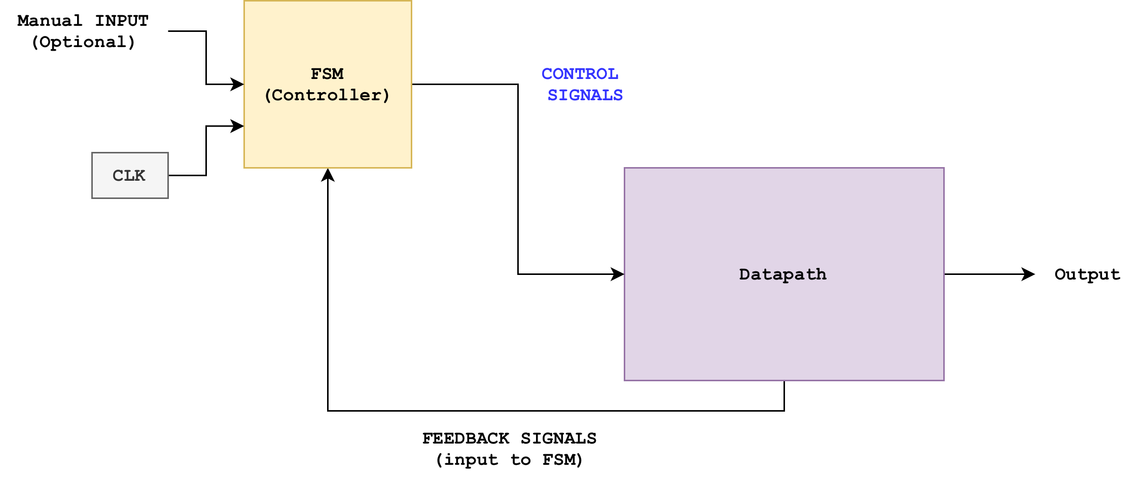
The interface is between the two intentionally simple:
- Controller to datapath: control signals
- Datapath to controller: status/feedback signals
Datapath
Before thinking about the controller and how many states it should have + logic, it helps to be very explicit about the datapath (hardware) that the controller (FSM) will drive. The datapath for this automated tester we are building should contain:
- Registered Adder Block (you can use either with or without write enable)
- Your
registered_rcathat takesa[7:0],b[7:0]and produces a registered sums[7:0]. - Internally, it already has:
- Input registers for
aandb. - A combinational RCA.
- An output register for
s
- Input registers for
- Your
- Test Vector Storage (ROM-like constants)
- Three constant arrays:
A_INPUTS[i]– list ofatest values.B_INPUTS[i]– list ofbtest values.SUMS[i]– expected sumsA_INPUTS[i] + B_INPUTS[i].
- These behave like a tiny read-only memory indexed by a test index.
- Three constant arrays:
- Test Index Register
- A
dffcalledindexthat stores which test case we are currently running. - Width is
log2(N)bits if you haveNtest vectors. - The controller can:
- Reset
indexto 0. - Increment
indexby 1, with wraparound atN.
- Reset
- A
- Expected Sum Pipeline
- From Lab 3, you should already know that since the adder output
sis registered, there is a latency between:- When a new
(a, b)is applied, and - When the corresponding
sbecomes valid.
- When a new
- To compare fairly, the expected sum must go through the same number of register stages as the real sum.
- From Lab 3, you should already know that since the adder output
- Comparator and Error Flag
- A combinational comparator that checks
s == expected_s. - This comparator outputs a flag that is
1ifs != expected_s.
- A combinational comparator that checks
-
You should also have a forced error mask driven by a DIP switch, which flips one bit of the adder output before comparison, so that you can demonstrate that the tester is actually checking something.
- LED Outputs (optional, good for debugging)
io_led[0]shows the currentstest value.io_led[1]shows the current adder’s sumsvalue.- A dedicated LED shows
error_flag, etc
The datapath should also receive a regular hardware clock (100Mhz) and not run on a human-visible slow clock.
Datapath big idea
If you change the control strategy, the datapath can stay exactly the same. That is the point of this lab.
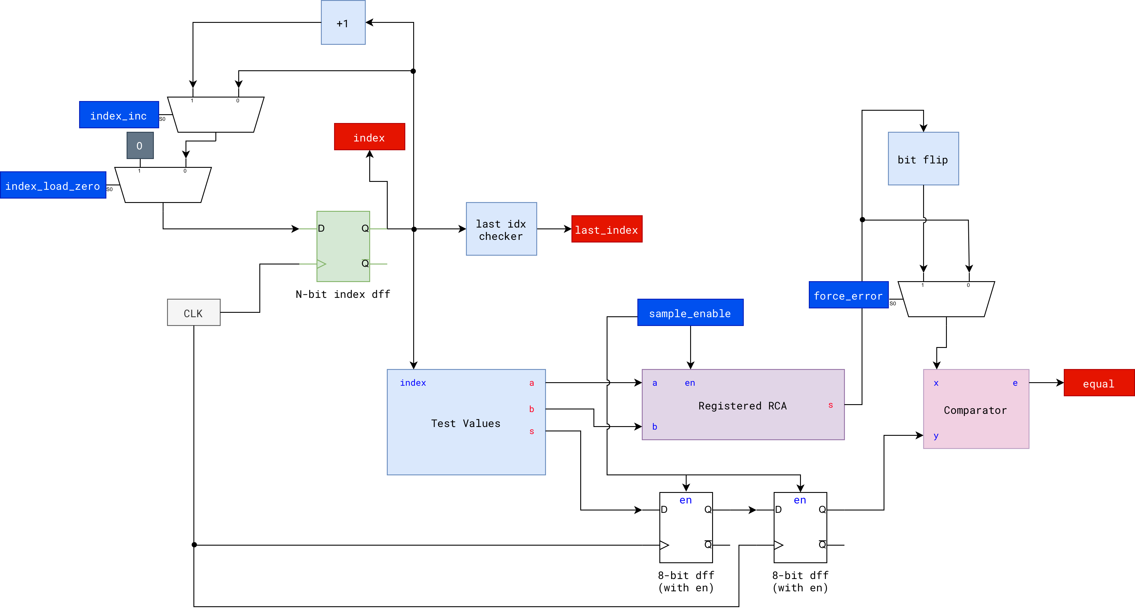
You should be able to draw the datapath of the system above. Try it on your own. Alternatively, you can see the proposed datapath in the appendix.
FSM controller
Now we give this datapath a small finite state controller.
This controller is the brain of the tester:
- It outputs control signals that decide what each part of the datapath does on each clock.
- It should receive
slow_clocksignal as input to indicate when we should change state, and button presses from user such asstart_button, etc. - It should also receive status/feedback signals from the Datapath to decide “what to do”
From the FSM notes, recall that the controller itself can be implemented as a Moore-style machine:
- It has a state register that stores the current state encoded in a few bits.
- It looks at some input flags from the datapath and decide what to do.
- It produces control outputs that drive the datapath.
Transition condition is written at the arrows (inputs), and the output signals at each state is written below the state bubble. The start state in the diagram below is IDLE.
A natural set of states for this automated tester is:
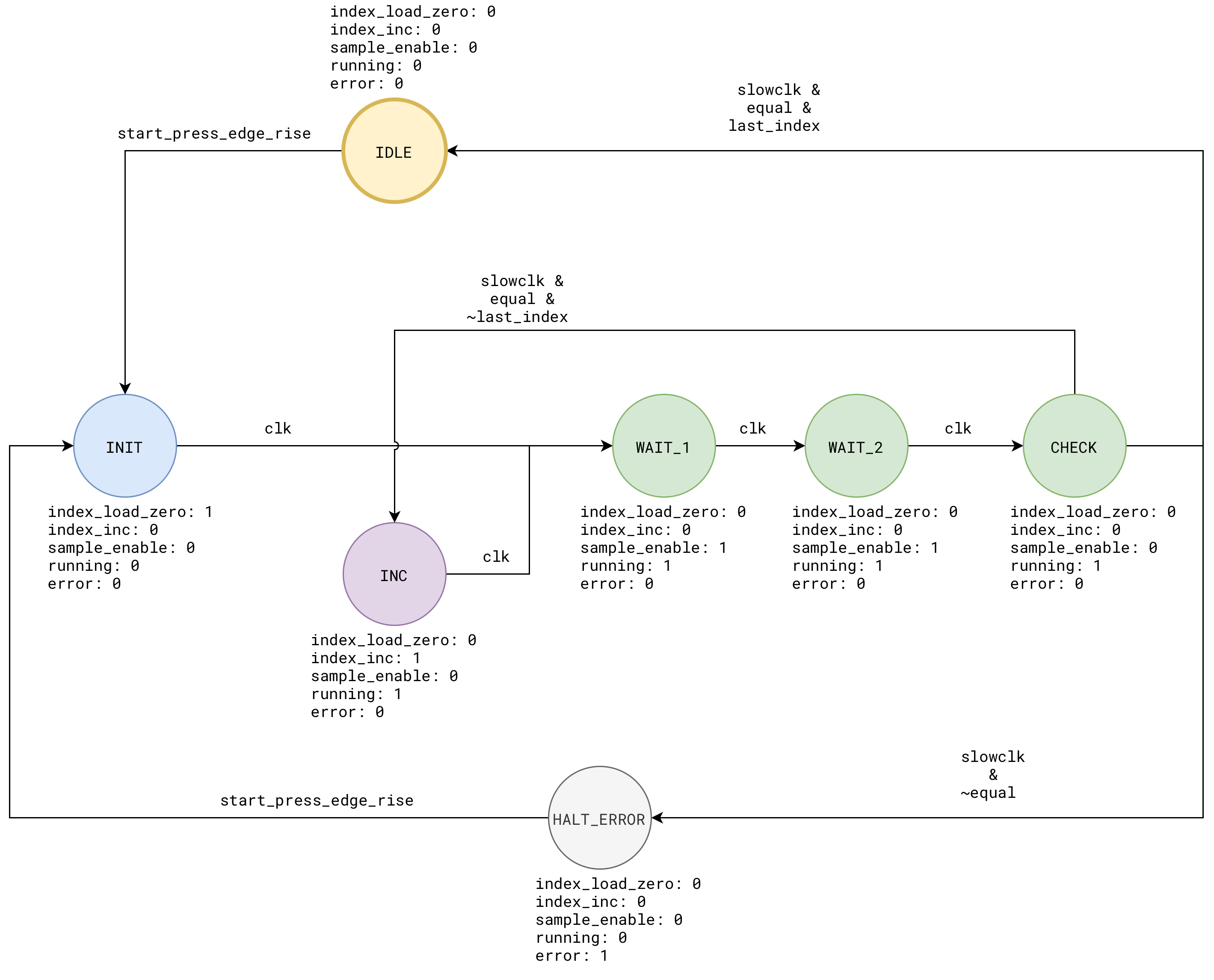
You can think of this as a tiny “hardware program” with 7 instructions: IDLE, INIT, INC, WAIT_1, WAIT_2, CHECK, and HALT.
The output signals written under each bubble is called control signals: they control and drive the datapath. Think of it like a train conductor’s action. The datapath is the railway system, it’s already built and all rails are already there. The conductor’s brain (FSM) decide what to do and their action is translated into control signals that drive the train (data).
Feedback Signals
Also known as status signals, these signals are produced by the datapath and fed to the FSM to typically trigger state transitions. The design is entirely up to you. For instance, you can have status/feedback signals like last_index to indicate whether we have reached the end of the test list and equal to indicate whether the adder’s output matches the answer key’s output.
Control Signals
These are the wires that cross the boundary between the FSM controller and the datapath hardware described earlier. The direction of these control signals is from controller to datapath.
Each control signal answers a very concrete question like:
- Should I advance to the next test vector now?
- Should the adder sample new inputs this cycle?
- Should I restart the tester?
We group them by the datapath component they talk to as defined in the datapath section above.
Control signals for the test index register
From the datapath we have:
Test Index Register
A
dffcalledindexthat stores which test case we are currently running. The controller can resetindexto0and increment it with wraparound.
To do this, the FSM should output two control signals:
index_load_zero: connects to theindexregister next-value logic- When
1for a cycle, the next value ofindexbecomes0. - Used in
INITto “start from test 0”.
- When
index_inc: also connects to theindexnext-value logic- When
1for a cycle, the next value ofindexbecomesindex + 1(with wraparound if needed). - Used in
CHECKwhen a test passes and we want to move on.
- When
Inside the datapath, we will typically implement a small MUX to implement this if-else logic. The FSM never touches index directly. It only set index_load_zero and index_inc.
Control signals for the registered adder and expected sum pipeline
From the datapath we have:
Registered Adder Block:
registered_rcawith internal input and output registers.Expected Sum Pipeline: must advance in sync with the adder.
Both should take a NEW test vector at the same time. The controller (fsm) needs to produce one:
sample_enable: connects to theenableinput ofregistered_rca, and you can also use it as the write enable for the expected sum pipeline- When
1, on the nextclkedge:- The adder registers produces new
aandbfromA_INPUTS[index]andB_INPUTS[index]. - The expected sum pipeline produces previous
SUMS[index].
- The adder registers produces new
- When
0, both keep their current values. - It is important to keep
sample_enable1for TWO cycles (which is whatWAIT_1andWAIT_2states are doing) - In
WAIT_1, theaandbregisters sample the test values - In
WAIT_2, thesregisters sample the adder’s sum output
- When
Control for “running” or “halt” status
From the FSM diagram:
HALTkeeps the failing case frozen and ignores further clock ticks.
You can make this explicit with a simple flag that can be routed to the LED so user knows whether the tester is running or not:
running: can be used to gate some datapath activity or to drive a status LED.running = 1inINC,WAIT_1/2,CHECK.running = 0inHALT,IDLE,INIT.
You are free to use running in different ways:
- As a signal to a status LED so humans can see “tester is alive”.
- As an extra condition on some control:
index_inc_effective = running && index_incsample_enable_effective = running && sample_enable
Inputs to the FSM from the datapath or top module
These are self-explanatory. They are the inputs that trigger FSM transitions.
rst- Comes from the global reset button.
- Typically resets both FSM state and datapath registers.
equal- Comes from the comparator that checks the possibly masked
sagainstexpected_s. equal = 1means “this test case passed”.
- Comes from the comparator that checks the possibly masked
last_index- Comes from simple logic on the
indexregister:last_index = (index.q == N-1); - Lets the FSM decide how to behave at the end of the test list (wrap around, stop on success, etc).
- Comes from simple logic on the
clkandslow_clock- To transition states accordingly
start_press- Remember to have button presses conditioned + passed through rising edge detector before used as FSM transition (see later sections for more information)
Summary
- The datapath has:
- Registers:
index,a,b,s, and expected sum pipeline - Combinational logic: ROM-like arrays, RCA, comparator, small MUXes
- Registers:
- The FSM controller has:
- A state register that stores seven states:
IDLE,INIT,FEED,WAIT_1,WAIT_2,CHECK,HALT. - Next-state logic that uses
rst,equal,last_index,slow_clock, andclk - Output logic that produces the control signals:
index_load_zeroindex_incsample_enableerrorrunning
- A state register that stores seven states:
The control signals live exactly on those arrows from the FSM block to the datapath block in the diagram. They are the “verbs” that make the datapath “do something” every slow clock tick.
Implementing an FSM in HDL
Implementing an FSM in HDL is pretty straightforward: you use a dff that holds your states and depending on status flags, decide whether to go to the next state or not.
Here’s a simple implementation.
List out the states
You can use enum in Lucid to encode each state.
    enum States {
        START,
        LOOP,
        CHECK_RESULT,
        HALT
    }
They will be auto computed as b00, b01, b10, b11.
Create the state dff
The
$widthfunction and$clog2functionThe
$widthfunction can be used on anenumto get the minimum number of bits to store a state value. If you have 8 states, then$width(States)returns3. Alternatively, you can use$clog2(NUM_STATES)if you knowNUM_STATESfrom the start.
dff states[$width(States)](#INIT(States.START), .clk(clk), .rst(rst))
Write the FSM logic
In the always body, all you need to do is to use the case statement to set the value of the state dff in the next cycle based on status flags, and produce outputs accordingly.
You can implement any logic you want in each state, but best if you stick to if-else or boolean logic so as not to blow up your design. Here’s an example of a simple FSM with 4 states, that increment some index register 3 times before going to HALT.
It has two outputs: 8-bit led_indicator and 2-bit index_value that determines the transition logic (whether to continue LOOP or HALT):
module simple_fsm (
    input clk,  // clock
    input rst,  // reset
    output led_indicator[8],
    output index_value[2]
) {

    enum States {
        START,
        LOOP,
        CHECK_RESULT,
        HALT
    }

    dff states[$width(States)](#INIT(States.START), .clk(clk), .rst(rst))
    dff index[2](.clk(clk), .rst(rst), #INIT(0))
    always {
        index_value = index.q
        states.d = states.q
        index.d = index.q
        led_indicator = 0

        case(states.q){
            States.START:
                led_indicator = 8h01
                index.d = 0
                states.d = States.LOOP

            States.LOOP:
                led_indicator = 8h0F
                index.d = index.q + 1
                states.d = States.CHECK_RESULT

            States.CHECK_RESULT:
                led_indicator = 8hF0
                if (~|(index.q ^ b10)){
                    states.d = States.HALT
                }
                else{
                    states.d = States.LOOP
                }

            States.HALT:
                led_indicator = 8hFF

        }
    }
}
For more examples, you’re encouraged to read this Alchitry official tutorial.
Curb the urge to overcomplicate things.
An FSM is super simple: you only need a
state dffand a whole bunch ofcasestatements. Within thecasestatement, you should specify ALL output signals.Ideally, you should have minimal logic within the FSM
cases, that is: avoid the urge to perform complex arithmetic operations like addition and multiplication there. This should be done in the datapath. You will learn more about this in the following weeks.
Test the FSM in Simulator
If you utilise the FSM as such, with onboard clock:
    // alchitry_top
    simple_fsm simple_fsm(.clk(clk),.rst(rst))


    always{
        // other code

        io_led[0] = simple_fsm.led_indicator
        io_led[1] = simple_fsm.index_value
    }
You will notice that the FSM runs so fast that it HALTs immediately:

This is because the clk supplied is at 1000Hz in the simulator, which is way TOO FAST for human eye to see. You need to slow down the fsm’s clock considerably to be able to view the state transition manually.
Slowing down the FSM clock
There are TWO ways to do this:
- Supply
slow_clocksignal (fromcounter) to the.clkport ofsimple_fsm, OR - Add
slow_clocksignal asinputto thesimple_fsmand perform transition or modification of ANYdffONLY ifslow_clockis 1
We will present BOTH ways to you and the pros and cons of each.
(Bad but quick) Method 1: use slow_clock as .clk that drives the FSM
    counter slow_clock(
        #DIV(9),
        .clk(clk),
        .rst(rst))

    simple_fsm simple_fsm(.clk(slow_clock.value),.rst(rst))
Pros: You can see the state transitions well, with minimal mental gymnastics to implement.
Cons: This is a bad practice for three reasons.
- Firstly, you lose the global reset for this reason

- Secondly, you make your FSM unresponsive by running on such a slow clock. See the gif below
- Thirdly (biggest reason): you can suffer from clock skew.
The moment you use a counter bit as a clock pin, you now have two clocks in your design:
- The real 100 MHz clock and
- Your derived slow clock.
These two clocks are not guaranteed to stay in sync with each other on real hardware. They can skew:
- The slow clock edge can arrive slightly earlier or later than expected relative to everything else,
- And that offset is unpredictable and changes between builds.
As a result, components driven by the slow clock and components driven by the 100 MHz clock cannot reliably talk to each other. Vivado (build) also cannot properly check whether your timing is safe, because it does not recognise the counter bit as a real clock. You get no warnings, the build succeeds, and the bug only shows up on hardware in ways that are very hard to trace.
See Custom Clock Pitfall for a full explanation of what goes wrong when you use data signal as clk input to other modules in your design.
There’s some workaround though to fix the reset issue (the first issue mentioned): if you’d like to reset the simple_fsm, you need to pass it as an input signal that you check at the end of your always block.
    // simple_fsm
    module simple_fsm (
        ...
        input manual_reset,
    ) {
        // instances

        always
        {
            // FSM cases

            // place this at the end to take precedence
            if (manual_reset){
                states.d = States.START
                index.d = 0
            }

        }
    }

    // alchitry_top
    simple_fsm simple_fsm(
        .clk(slow_clock.value),
        .rst(rst),
        .manual_reset(io_button[0])) // link to a button
You would have to press and hold io_button[0] for at least of 1 slow_clock period to reset (the FSM feels unresponsive):

The io_button[0] manual reset signal should be valid across rising edge of slow_clock signal to be captured and propagated to simple_fsm. Otherwise, if it is only valid briefly in-between rising slow_clock edges, then it will be ignored. This is the behavior of sequential logic.
(GOOD) Method 2: use slow_clock with edge_detector as input to the FSM
This method is your instructors’ preferred way, but it has way higher learning curve to master.
In this method, we run simple_fsm with the original clk signal, but add conditional logic to transition within each case only when slow_clock edge is 1. This way our FSM remains responsive and only conditionally transition when slow_clock is 1.
To do this, we need to pass slow_clock signal through an edge detector. Do you know why?
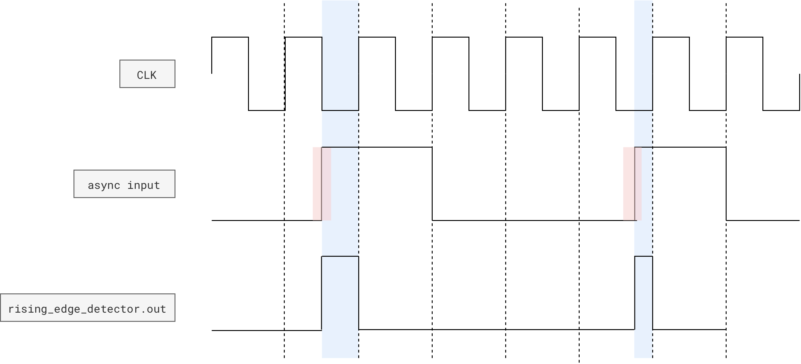
Edge detector
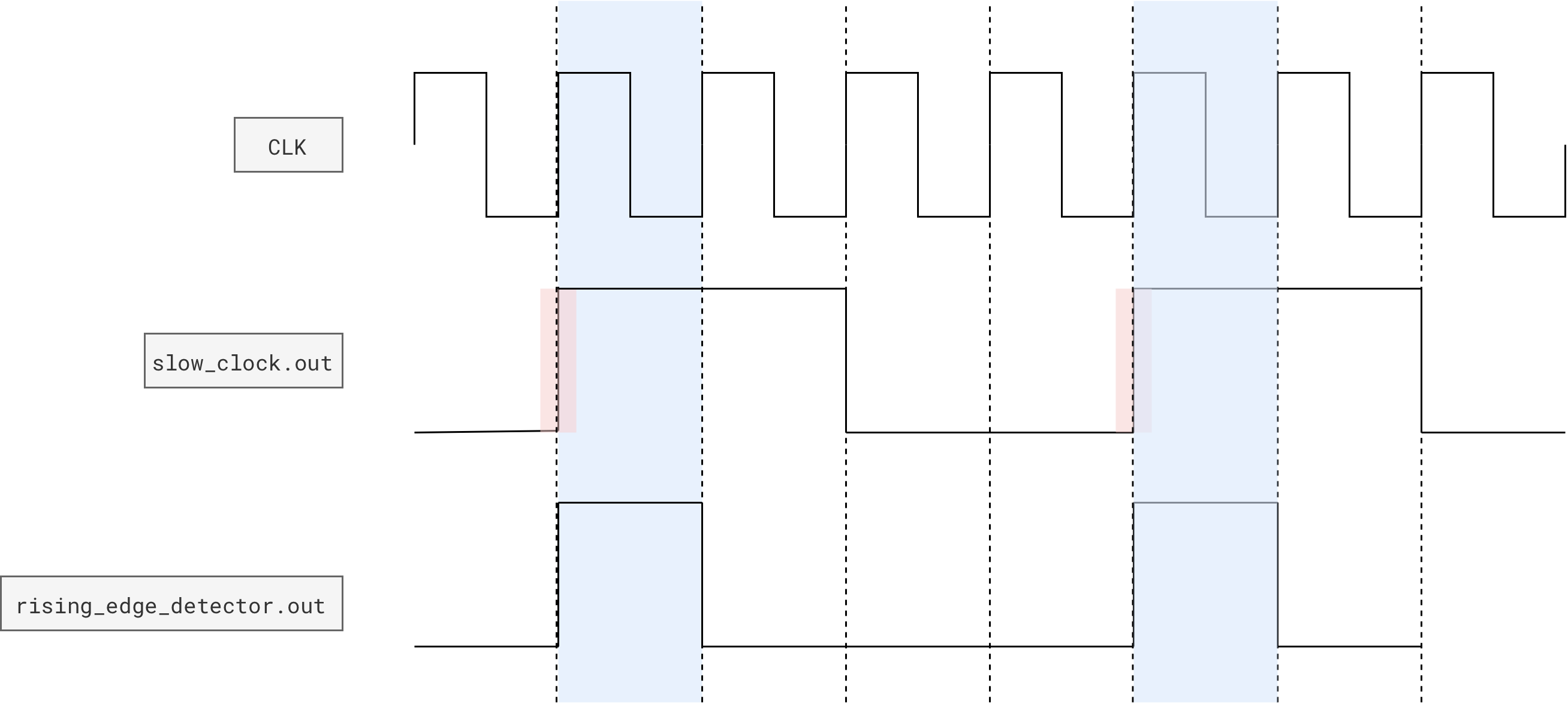
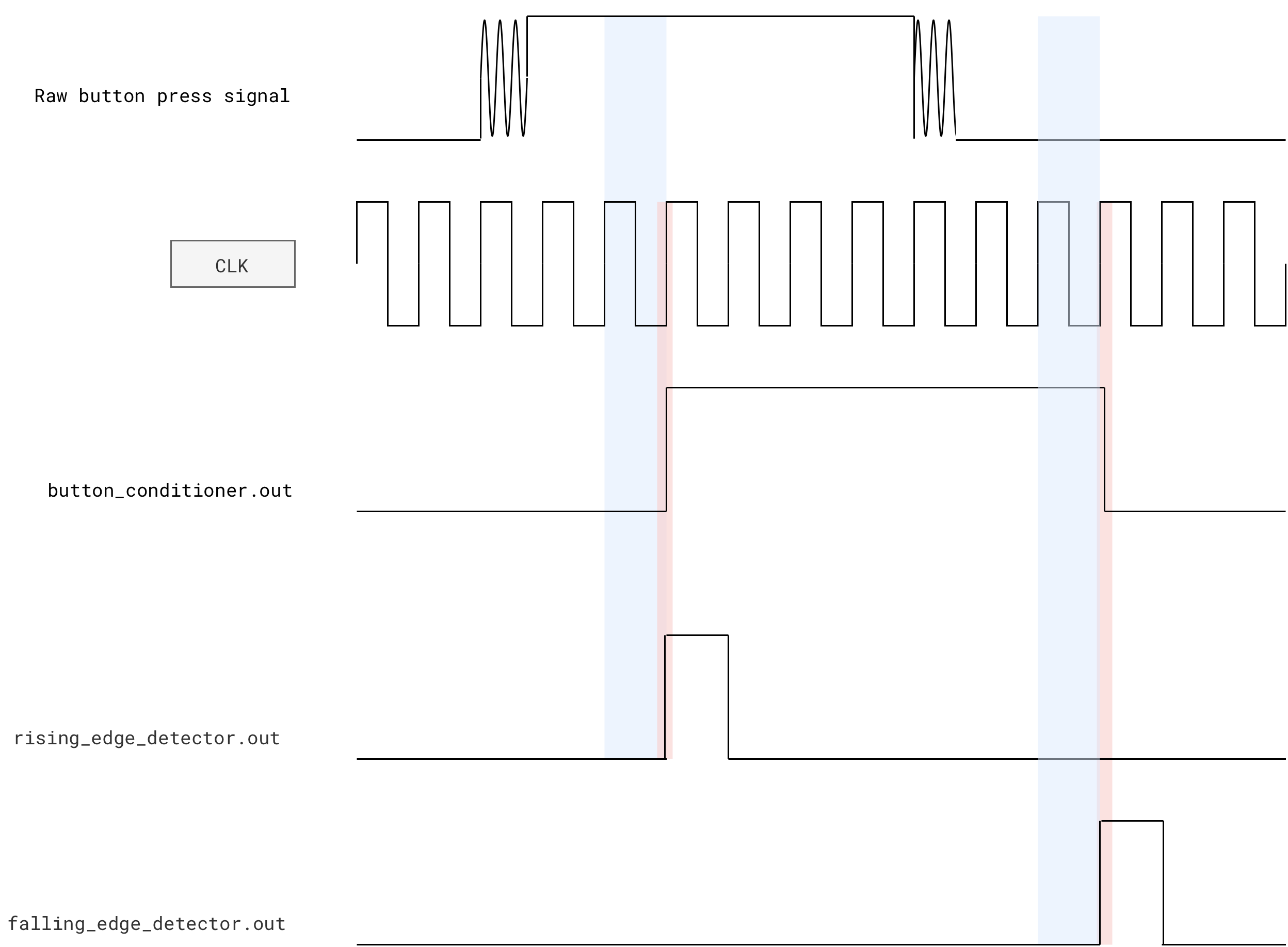
An edge detector produces a valid
1when detecting a rising edge of its input signal for as long as oneclkperiod.
This diagram illustrates the concept:
- Whenever the
slow_clocksignal turns from0to1(pink highlight), - The edge detector will output a
1for as long as1clkperiod in the next nearest one (blue highlight)
Race Condition
Notice how in the diagram above, for illustration purposes, we show that the slow clock produces a
1in clk cycletand edge detector produces a1in the same cyclet. This behavior might differ depending on the simulator use and might behave differently in hardware as well. This is called a race condition.A synchronous FF samples its input at the clock edge. If you also change the input at the exact same edge in simulation, you are modeling an impossible or undefined physical situation (setup/hold violation). In real hardware this is not a clean “either-or”, it can produce metastability. In simulation it shows up as nondeterminism based on event ordering.
In short, the edge detector might produce a
1in this clock cycletor at cyclet+1. However, since the onboard clk runs really fast, it won’t affect the usability of your hardware. It’s a minor difference of whether the button press is detected in this cycle or the next.
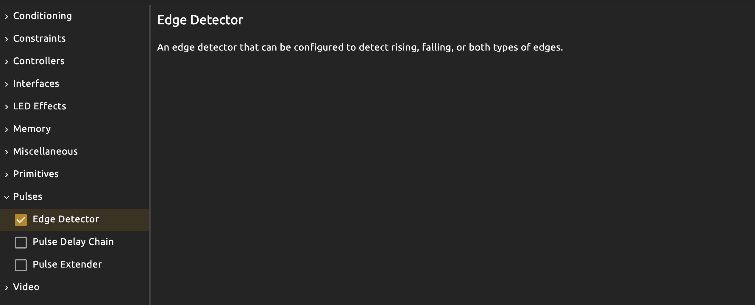
Add this component to your project:
Then instantiate it in your simple_fsm, and use it in each of the case logic to allow transition + permanent dff changes ONLY when slow_clock is 1.
// simple_fsm
module simple_fsm (
    // other ports
    input slow_clock
) {

    edge_detector rising_edge(.clk(clk),.in(slow_clock),#RISE(1),#FALL(0))
}

always {
        // other code

        case(states.q){
        States.START:
            led_indicator = 8h01
            index.d = 0
            if (rising_edge.out)
                states.d = States.LOOP

        States.LOOP:
            led_indicator = 8h0F

            if (rising_edge.out){
                index.d = index.q + 1 // this should be inside the if-clause, it can't be outside
                states.d = States.CHECK_RESULT
            }


        States.CHECK_RESULT:
            led_indicator = 8hF0
            if (~|(index.q ^ b10)){
                if (rising_edge.out)
                    states.d = States.HALT
            }
            else{
                if (rising_edge.out)
                    states.d = States.LOOP
            }

        States.HALT:
            led_indicator = 8hFF

    }

}
Then use it as such:
// alchitry_top
simple_fsm simple_fsm(.clk(clk),.slow_clock(slow_clock.value),.rst(rst))
This way, your global reset still works (and is responsive! No more press and hold to reset), but you end up with lots of inevitable boilerplate: repeatedly checking (if rising_edge.out) in each case where dff assignment happens.

Conceptually, you allow the FSM to REMAIN IN STATE, until rising_edge.out == 1. For instance:
- the FSM would stay at state
LOOPand theled_indicatorshows8h0F. It is actually “looping” at everyclkcycle, that is the value ofdffstate is repeatedly written asStates.LOOP - When
rising_edge.out == 1, we would finally write a different value intostatesdff andindexdff, allowing the fsm to “advance” at that exact moment - the FSM is actually still “responsive”, running at
clkfrequency
This is inherently different from method 1, where you slow down the entire FSM with slow_clock, rendering it rather unresponsive as it will only be able to detect input (like the manual_reset button) if its held long enough, roughly covering one period of slow_clock.
Common mistakes when dealing with FSM clock
Mistake 1: tried to “refactor” by moving the if-clause out of the cases
This mistake is very subtle, and you will only realise that you lose certain functionalities if you try to incorporate some button presses.
Take a look at this example and try it out:
module simple_fsm (
    input clk,  // clock
    input rst,  // reset
    input slow_clock,
    output led_indicator[8],
    output index_value[2]
) {

    enum States {
        START,
        LOOP,
        CHECK_RESULT,
        HALT
    }

    dff states[$width(States)](#INIT(States.START), .clk(clk), .rst(rst))
    dff index[2](.clk(clk), .rst(rst), #INIT(0))

    edge_detector rising_edge(.clk(clk),.in(slow_clock),#RISE(1),#FALL(0))

    always {
        index_value = index.q
        states.d = states.q
        index.d = index.q
        led_indicator = 0

        if(rising_edge.out){    // this can be disastrous
            case(states.q){
                States.START:
                    led_indicator = 8h01
                    index.d = 0
                    states.d = States.LOOP

                States.LOOP:
                    led_indicator = 8h0F
                    index.d = index.q + 1
                    states.d = States.CHECK_RESULT

                States.CHECK_RESULT:
                    led_indicator = 8hF0
                    if (~|(index.q ^ b10)){
                        states.d = States.HALT
                    }
                    else{
                        states.d = States.LOOP
                    }

                States.HALT:
                    led_indicator = 8hFF
            }
        }


    }
}
Observation:
- It seems like the fsm runs but you lose your status
led_indicator(seemingly) - Global reset works (makes sense, because you are using global clock still)

The problem becomes worse if you try to add “interaction” to the FSM, for instance, a START button that results in transition from HALT to START once per press.
Typically, we send interactive button presses through an edge detector so that each physical press produces a single, one-cycle pulse. This lets the circuit respond to the moment the button is pressed, rather than the entire time it is held down, so a held button does not retrigger the action on every clock cycle.
// simple_fsm
module simple_fsm (
    input clk,  // clock
    input rst,  // reset
    input slow_clock,
    input start,
    output led_indicator[8],
    output index_value[2]
) {

    enum States {
        START,
        LOOP,
        CHECK_RESULT,
        HALT
    }

    dff states[$width(States)](#INIT(States.START), .clk(clk), .rst(rst))
    dff index[2](.clk(clk), .rst(rst), #INIT(0))

    edge_detector rising_edge(.clk(clk),.in(slow_clock),#RISE(1),#FALL(0))
    edge_detector rising_edge_start(.clk(clk), .in(start), #RISE(1), #FALL(0))
    always {
        index_value = index.q
        states.d = states.q
        index.d = index.q
        led_indicator = 0

        if(rising_edge.out){        // this might be disastrous
            case(states.q){
                States.START:
                    led_indicator = 8h01
                    index.d = 0
                    states.d = States.LOOP

                States.LOOP:
                    led_indicator = 8h0F
                    index.d = index.q + 1
                    states.d = States.CHECK_RESULT

                States.CHECK_RESULT:
                    led_indicator = 8hF0
                    if (~|(index.q ^ b10)){
                        states.d = States.HALT
                    }
                    else{
                        states.d = States.LOOP
                    }

                States.HALT:
                    led_indicator = 8hFF
                    if(rising_edge_start.out){ // this might go undetected
                        index.d = 0
                        states.d = States.START
                    }
            }
        }


    }
}
Use it as such:
// alchitry_top
simple_fsm simple_fsm(.clk(clk),.slow_clock(slow_clock.value),.rst(rst),.start(io_button[1]))
The logic might seem “right” but it won’t even work. Towards the end of the gif below, we show what the “correct behavior” should be:
- The “start” button triggers transition from
HALTtoSTARTonly, not from other states toSTART - Global reset works as per normal
- This happens because we move back the
if(slow clock edge rise detected) clause within eachcaseand utilise a button conditioner (see later section)

Checkoff
Why is this so? Figure it out as a team. This might be one of the checkoff questions asked by your TA.
Mistake 2: not using an edge detector
Try this code and notice that we NEVER have this transition: CHECK_RESULT to LOOP as index_register seemingly goes straight from 0 to 2 (skipping 1).
// simple_fsm
module simple_fsm (
    input clk,  // clock
    input rst,  // reset
    input slow_clock,
    output led_indicator[8],
    output index_value[2]
) {

    enum States {
        START,
        LOOP,
        CHECK_RESULT,
        HALT
    }

    dff states[$width(States)](#INIT(States.START), .clk(clk), .rst(rst))
    dff index[2](.clk(clk), .rst(rst), #INIT(0))

    always {
        index_value = index.q
        states.d = states.q
        index.d = index.q
        led_indicator = 0

        case(states.q){
            States.START:
                led_indicator = 8h01
                index.d = 0
                if (slow_clock)
                    states.d = States.LOOP

            States.LOOP:
                led_indicator = 8h0F

                if (slow_clock){
                    index.d = index.q + 1
                    states.d = States.CHECK_RESULT
                }


            States.CHECK_RESULT:
                led_indicator = 8hF0
                if (~|(index.q ^ b10)){
                    if (slow_clock)
                        states.d = States.HALT
                }
                else{
                    if (slow_clock)
                        states.d = States.LOOP
                }

            States.HALT:
                led_indicator = 8hFF

        }


    }
}

Checkoff
Why is this so? Figure it out as a team. This might be one of the checkoff questions asked by your TA.
Processing Button Presses
This is the final piece of knowledge required to operate your FSM controller.
Managing button presses
We can’t use button presses directly to trigger the FSM because of the significant speed difference between human reactions and the onboard FPGA clock
clk(100 MHz on hardware, 1000Hz on simulator).When a button, such as
io_button[i], is pressed, it will remain in the1state for MANY defaultclkcycles, as a typical button press lasts milliseconds, while each clock cycle occurs in nanoseconds.As a result, the FSM might rapidly toggle between states multiple times during a single press, instead of transitioning just once-per-press as intended.
In video games, this has the same logic:
- You would detect a jump trigger (press space once)
- Then your character will jump exactly once
- If you continue holding space, no further jump is made
It is almost always the case to use an edge_detector (rising/falling, depending on which press you are detecting, down or release) AND a button_conditioner to make button presses works properly for FSM driven by the regular clk.
Button Conditioner
Button Conditioner
Button Conditioner: This module will synchronize and debounce a button input so that you can reliably tell when it is pressed
When you connect a physical pushbutton directly to your FPGA, the signal you see on the input pin is not a clean, single transition from 0 to 1. Two big problems show up:
-
Mechanical bounce: When you press or release the button, the contacts literally bounce for a few milliseconds. Electrically, this looks like a fast sequence of
0→1→0→1→0before it finally settles. If you sample this with a fast clock, your circuit thinks you pressed the button many times. -
Asynchronous to the clock: The button is controlled by a human, so it changes value at arbitrary times relative to the FPGA clock and might not fulfil
tsetupandthold. If you feed that straight into sequential logic, you can get metastability and unpredictable behaviour.
Here’s a simplified illustration:
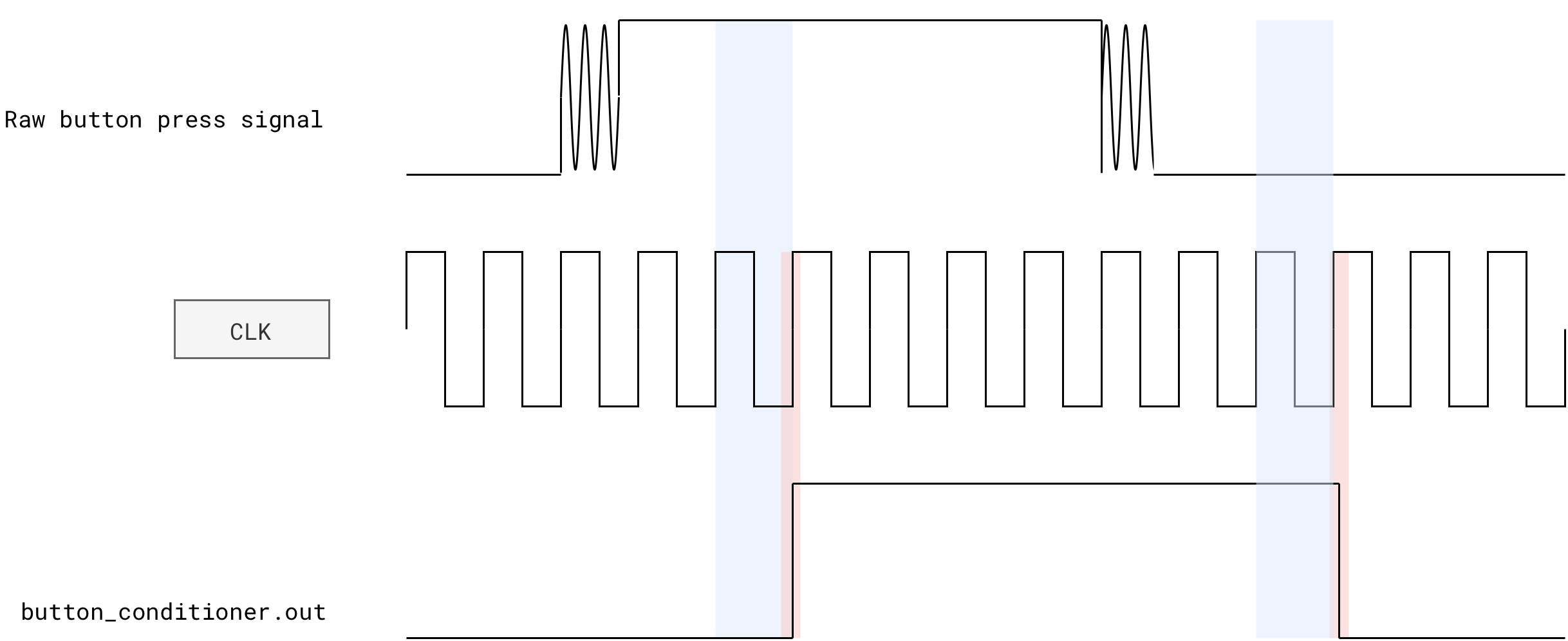
The raw signal typically has:
- Long low level (0)
- Around the press moment, several fast 0/1 transitions before it settles high
- Long high level (1) while the button is held
- Around the release moment, again several fast 0/1 transitions before it settles low
A Button Conditioner solves both issues:
- It first synchronizes the RAW button signal into the FPGA clock domain using a small chain of D flip flops. This makes sure downstream logic only ever sees changes that are aligned with clock edges (pink highlight in figure above).
- It then debounces the signal by WAITING (blue highlight in the figure above) until the input has stayed stable (all
0or all1) for a certain number of clock cycles before accepting the new value. Short spikes due to bouncing are filtered out.
Button Conditioner + Edge Detector
As mentioned before, the conditioner also used with edge detector that converts the debounced level into a ONE cycle pulse on each press. That pulse is easier to use as a discrete “press event” in an FSM or counter.
With this setup, a button conditioner turns a noisy, asynchronous, human controlled signal into a clean, clock aligned signal where one press is equal to one event signal that your digital logic can safely use.
You must run the button through the synchronizer/debouncer before feeding it into the default Alchitry edge detector.
Based on its implementation, the Alchitry default
edge_detectoroutputs a1in this clock cycle since its output is combinational. That means it should receive aninsignal that’s synchronized with theclk, otherwise the output will be asynchronous.See appendix for more detail.
Using button presses properly in an FSM
Assume you want to process a start signal to transition from HALT to START state. You should pass the conditioned start signal through an edge detector:
module simple_fsm (
    input clk,  // clock
    input rst,  // reset
    input slow_clock,
    input start, // assume already conditioned
    output led_indicator[8],
    output index_value[2]
) {

    enum States {
        START,
        LOOP,
        CHECK_RESULT,
        HALT
    }

    dff states[$width(States)](#INIT(States.START), .clk(clk), .rst(rst))
    dff index[2](.clk(clk), .rst(rst), #INIT(0))

    edge_detector rising_edge(.clk(clk),.in(slow_clock),#RISE(1),#FALL(0))
    edge_detector rising_edge_start(.clk(clk), .in(start), #RISE(1), #FALL(0))

    always {
        index_value = index.q
        states.d = states.q
        index.d = index.q
        led_indicator = 0

        case(states.q){
            States.START:
                led_indicator = 8h01
                index.d = 0
                if(rising_edge.out)
                    states.d = States.LOOP

            States.LOOP:
                led_indicator = 8h0F
                if(rising_edge.out){
                    index.d = index.q + 1
                    states.d = States.CHECK_RESULT
                }

            States.CHECK_RESULT:
                led_indicator = 8hF0
                if (~|(index.q ^ b10)){
                    if(rising_edge.out){

                        states.d = States.HALT
                    }
                }
                else{
                    if(rising_edge.out){
                        states.d = States.LOOP
                    }
                }

            States.HALT:
                led_indicator = 8hFF
                // always detected
                if(rising_edge_start.out){
                    index.d = 0
                    states.d = States.START
                }
        }
    }
}
The “conditioning” is typically done in the top module, as it is part of “input cleanup” and not system logic:
    // alchitry_top
    button_conditioner start_button(.clk(clk), #CLK_FREQ(1000), .in(io_button[1])) // simulator clock
    simple_fsm simple_fsm(.clk(clk),.slow_clock(slow_clock.value),.rst(rst),.start(start_button.out))
Here’s the result with button conditioning (reliable outcome):

And here’s the result without button conditioning (unreliable start button press detection):

Building the Automated Register Adder Tester
Suggested design
You are to test the functionality of your REGISTERED 8-bit RCA (registers a, b, and s are required!) automatically here by using an fsm. You may choose to use write-enabled register or not. Your implementation should adapt accordingly.
Similar to the previous lab, you can create constants that stores the following:
A_INPUTS[i]: the i-th test value for operanda.B_INPUTS[i]: the i-th test value for operandb.SUMS[i]: the expected sumA_INPUTS[i] + B_INPUTS[i].index: a DFF that stores which test case we are currently applying.
If you have N test cases, then A_INPUTS, B_INPUTS, and SUMS are all N by 8 array. index has the size of log2(N) bits.
On each slow clock tick (for example near 1 Hz):
indexincrements by 1 (wrapping around at the end).- The current
aandbinputs toregistered_rca_enare taken fromA_INPUTS[index.q]andB_INPUTS[index.q]. - The adder computes
s. - Hardware compares
swith pipelinedSUMS[index.q]. - The LEDs display
a,b,s, and an error flag.
$is_sim()
The real FPGA hardware has 100Mhz onboard clock. As such, you need to set the DIV of the slow_clock into 28 or 29 to make the hardware output human-readable.
You can conditionally set the DIV of the slow_clock to 9 or 28 using inbuilt function $is_sim() depending on whether we are running simulation in software or hardware:
    button_conditioner start_button(.clk(clk), #CLK_FREQ($is_sim() ? 1000 : 100000000), .in(io_button[1]))
    counter slow_clock(#DIV($is_sim()? 9 : 28), .clk(clk), .rst(rst), #SIZE(1))
Test on Simulator First
Before building your project, you shall test your tester in the simulator first.
You can set the following interface:
io_led[0]: index register valueio_led[1]: registered addersvalueio_led[2]: expectedsvalue from the sum pipelineled[5:0]: indicates the states we are at (optional):IDLE:00001CHECK:00010HALT_ERROR:00011
led[7]: indicates theerrorbit

Here’s a sample demo using the simulator. The usage of seven segment is optional. You can read this guide if you are interested. For now, you can use basic io LED to show current test index ID.
- In this sample demo, we have 16 test cases. As demo purposes, we used the seven segments. You are not required to use it for checkoff.
io_button[0]is used to start/restart the testerio_dip[2][7]will force bit-flip the adder’s output and induce and error, to demonstrate that our tester can show error. This is a forced error.- Once error is induced, the tester stops at the test-case index of that error
- You can restart again by pressing
io_button[0]

Build and flash to FPGA
Once your tester works in the simulator, you should build the project and flash it to the FPGA. To do this, you will need to have Vivado installed. Refer to the installation guideline if you have not read them. It explains:
- How to install Vivado
- How to build your project
- How to flash them to your FPGA
Once Vivado location is set, click the hammmer button to begin building:

You should be able to demo using the hardware exactly what you see in the simulator:
Checkoff
This checkoff (2%) is done as a group.
- It consists of hardware FPGA demo (1%) and QnA (1%).
- Contact your cohort TAs and make appointment to meet them in-person (outside of class hour).
For checkoff, your group must show the automated tester working on the FPGA : it steps through multiple test cases automatically, shows correct values for a working adder, turns on the error indicator and freezes on the failing case when you inject an error, and cleanly restarts with a button press once the fault is removed.
Details:
- The adder is driven automatically by a sequence of test vectors (no manual DIP changes needed during the demo).
io_led[0]shows the current test case valuea,io_led[1]shows the current test caseb, andio_led[2]shows the computed sums.- The tester steps through at least 8 different
(a, b)pairs at a slow, human-visible rate (about 1 Hz). - The
errorindicator LED remains off for all test cases when the adder is implemented correctly. - If you intentionally break the adder (for example, force one bit of the sum to 0), the
errorLED turns on for at least one test case- Then, the tester should
HALTand show the current test case id (it can either be in decimal or binary format) - User can restart the tester and it should run as per normal again once forced error is removed
- Then, the tester should
- TAs will ask you two questions (same protocol as lab 2) about any code written in your project
Summary
In this lab, we move from ad-hoc testbenches to a self-checking hardware tester built using the classic controller–datapath structure. The datapath becomes a fixed circuit containing registers, the registered RCA, constant test-vector arrays, a pipelined expected sum, and a comparator. The controller becomes a small FSM that decides when data moves. This is the same architectural pattern we will use next week when we introduce a simple ISA and build the datapath of a toy CPU.
The datapath holds test vectors (A_INPUTS, B_INPUTS, SUMS) and steps through them with an index register. Each pair flows through the registered RCA, the expected sum is delayed to match the adder’s latency, and the outputs are compared. We can flip bits deliberately to prove that the tester detects errors, and we expose the key signals on LEDs or seven-segment displays for easy observation.
The FSM runs on the fast clock but only performs meaningful transitions on slow-clock edges. To support clean interaction, we debounce and synchronise button inputs with a button_conditioner and convert presses into one-cycle pulses using an edge_detector.
A few key control responsibilities:
- Reset or increment the test index.
- Enable sampling of new
(a, b)values and expected sum. - Decide when to halt on mismatch, and when to restart on a button press.
Appendix
Proposed Datapath
Alchitry Edge Detector
The edge detector provided by Alchitry Labs is:
/*
   Edge Detector: This module will detect when there is an edge on 'in' and will
   set 'out' high for that clock cycle. You can specify what type of edge you
   want to look for by setting 'RISE' to 1 for rising edges and/or 'FALL' to 1
   for falling edges.
*/

module edge_detector #(
    RISE = 1 : RISE == 0 || RISE == 1,
    FALL = 1 : FALL == 0 || FALL == 1
)(
    input clk,  // clock
    input in,   // input signal
    output out  // edge detected
) {

    // need to save the previous state of 'in'
    dff last(.clk(clk))

    always {
        out = 0 // default to 0

        last.d = in // save the input

        // if looking for rising edges
        if (RISE)
        // if there is a rising edge
            if (in == 1 && last.q == 0)
                out = 1 // set output flag

        // if looking for falling edges
        if (FALL)
        // if there is a falling edge
            if (in == 0 && last.q == 1)
                out = 1 // set output flag
    }
}
The subtlety is in WHEN in is allowed to change.
last.qis the previous value ofin, sampled on the last rising edge ofclk.outis combinational, computed from the currentinand the storedlast.q.
So in terms of logic:
out = RISE &  in & ~last.q   OR
      FALL & ~in &  last.q
Case 1: input is synchronous (what you want with a button conditioner)
If in only changes on rising edges of clk (for example it is the debounced button output or any flop output on the same clock), then:
- At the clock edge where
ingoes0to1,last.qstill holds0. - Immediately after that edge, the condition
in == 1 && last.q == 0is true, sooutbecomes 1. outstays 1 for the whole cycle, until the next rising edge updateslast.qto 1. After that,in == 1 && last.q == 0is false again, sooutgoes back to 0.
So with a synchronous input the pulse is exactly one full clock period long, aligned with the cycle where the edge happened.
That matches the module description: “set out high for that clock cycle”.
Case 2: input changes in the middle of the clock period
The big question
If an input
inbecomes1in the middle of the current clock cycle, is the edge detector 1 for the next rising edge fully 1 period or just from now till next edge?
With this implementation:
- Suppose
inwas0at the last clock edge, and in the middle of the cycle it flips to1. last.qis still0until the next rising edge.- As soon as
inflips to 1, the conditionin == 1 && last.q == 0becomes true, sooutbecomes1immediately, and stays1until the next rising edge, wherelast.qupdates to1and makes the condition false.
So physically:
outis1from “now” until the next edge, not a full period.- At the next rising edge, downstream flip flops will see
out = 1at that instant, then almost immediately after that edge,outdrops to0again, but still fulfils dynamic discipline at the next clock cycle (feeding a1)
From the point of view of any synchronous logic that samples out on clock edges, this probably still behaves like a one-cycle pulse.
Summary
If button conditioner is used with an edge detector, button conditioner’s output is synchronized to the clock.
The edge detector raises out (produce a 1) for exactly one clock cycle when the debounced button changes from 0 to 1 (or 1 to 0). Downstream logic that is clocked by the same clk will see a single-cycle pulse for each press.
For asynchronous inputs, the pulse width is “from the edge until the next clock” and you should not rely on it.
That is precisely why you must run the button through the synchronizer/debouncer before feeding it into this edge detector.