 50.002 CS
- \(\beta\) Trivia (Basic)
- \(\beta\) Assembly Language (Basic)
- Non \(\beta\) Architecture Benchmarking (Basic)
- Clumsy Lab Assistant (Basic)
- New Beta Instruction (Basic)
- Another New Beta Instruction (Basic)
- Memory Encoding (Basic)
50.002 Computation Structures
Information Systems Technology and Design
Singapore University of Technology and Design
Beta CPU Datapath
Each topic’s questions are grouped into three categories: basic, intermediate, and challenging. You are recommended to do all basic problem set before advancing further.
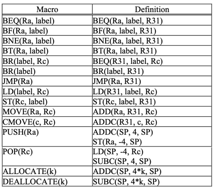
Before you proceed, we suggest you explore the Beta simulator bsim and read the beta documentation given in the course handout, especially this section called Convenience Macros that makes it easier to express certain common operations.
\(\beta\) Trivia (Basic)
-
In an unpipelined Beta implementation, when is the signal
RA2SELset to1?Show AnswerThe
RA2SELsignal is set to1when executing aSTinstruction. WhenRA2SELis1the 5-bitRcfield of the instruction is sent to theRA2port of the register file, causingReg[Rc]to be sent to the write data port of main memory. -
In an unpipelined Beta implementation, when executing a
BR(foo,LP)instruction to call procedurefoo, what shouldWDSELshould be set to?Show AnswerBR(foo,LP)is a **macro** forBEQ(R31,foo,LP). AllBNE/BEQinstructions save the address of the following instruction in the specified destination register (LPin the example instruction). SoWDSELshould be set0, selecting the output of thePC+4logic as the data to be written into the register file. -
The minimum clock period of the unpipelined Beta implementation is determined by the propagation delays of the datapath elements and the amount of time it takes for the control signals to become valid. Which of the following select signals should become valid first in order to ensure the smallest possible clock period:
PCSEL, RA2SEL, ASEL, BSEL, WDSEL, WASEL?Show AnswerTo ensure the smallest possible clock period
RA2SELshould become valid first. TheRA2SELMUX must produce a stable register address before the register file can do its thing. All other control signals affect logic that operates after the required register values have been accessed, so they don't have to be valid until later in the cycle.
\(\beta\) Assembly Language (Basic)
What does the following piece of Beta assembly do? Hand assemble the beta assembly language into machine language.
I = 0x5678
B = 0x1234

LD(I,R0) -- (1)
SHLC(R0,2,R0) --  (2)
LD(R0,B,R1) -- (3)
MULC(R1,17,R1) -- (4)
ST(R1,B,R0)  -- (5)
Finally, what is the result stored in R0?
The machine language is:
I = 0x5678
B = 0x1234
0x601F5678 || LD(R31,I,R0) -> 011000 00000 11111 0101 0110 0111 1000
0xF0000002 || SHLC(R0,2,R0) -> 111100 00000 00000 0000 0000 0000 0010
0x60201234 ||LD(R0,B,R1) -> 011000 00001 00000 0001 0010 0011 0100
0xC8210011 ||MULC(R1,17,R1) -> 110010 00001 00001 0000 0000 0001 0001
0x64201234||ST(R1,B,R0) -> 011001 00001 00000 0001 0010 0011 0100
- Line 1: move the content of the memory unit at
EA=Ito registerR0 - Line 2: the content of
R0is multiplied by 4 and stored back at registerR0 - Line 3: move the content of memory address
EA:EA=B+ content of registerR0; to registerR1. - Line 4: The content of register
R1is multiplied by 17 and stored back at registerR1. - Line 5: Store / copy the content of register R1 to the memory unit with address
EA:EA=B+ content of registerR0.
R0 is the content of memory address `I`: Mem[I] multiplied by 4.
Non \(\beta\) Architecture Benchmarking (Basic)
A local junk yard offers older CPUs with non-Beta architecture that require several clocks to execute each instruction. Here are the specifications:
\[\begin{matrix} \text{Model} & \text{Clock Rate} & \text{Avg. clocks per Instruction}\\ \hline x & 40 Mhz & 2.0\\ y & 100 Mhz & 10.0\\ z & 60 Mhz & 3.0\\ \end{matrix}\]You are going to choose the machine which will execute your benchmark program the fastest, so you compiled and ran the benchmark on the three machines and counted the total instructions executed:
-
x:3,600,000instructions executed -
y:1,900,000instructions executed -
z:4,200,000instructions executed
Based on the above data, which machine would you choose?
First we find out the time taken to execute those instructions: $$x: \frac{3.6M}{40M / 2} = 0.18s$$ $$y: \frac{1.9M} {100M / 10} = 0.19s$$ $$z: \frac{4.2M}{60M / 3} = 0.21s$$ From the result above, `x` is the fastest machine. Hence we choose `x`.
Clumsy Lab Assistant (Basic)
Notta Kalew, a somewhat fumble-fingered lab assistant, has deleted the opcode field from the following table describing the control logic of an unpipelined Beta processor.

-
Help Notta out by identifying which Beta instruction is implemented by each row of the table.
Show AnswerFrom first row to the last:
SUBC, BEQ, LDR, CMPEQ, ST. -
Notta notices that
WASELis always zero in this table. Explain briefly under what circumstancesWASELwould be non-zero.Show AnswerWASELis1if an interrupt, an illegal opcode is trapped, or a fault occurs. WhenWASELis1, it selectsXPas the write address for the register file;Reg[XP]is where we store the currentPC+4whenever there is an interrupt, a fault, or an illegal opcode. -
Notta has noticed the following C code fragment appears frequently in the benchmarks:
int *_p; /* Pointer to integer array */
int i,j; /* integer variables */

...

j = p[i]; /* access ith element of array */
The pointer variable p contains the address of a dynamically allocated array of integers. The value of p[i] is stored at the address Mem[p +4i] where p and i are locations containing the values of the corresponding C variables. On a conventional Beta this code fragment is translated to the following instruction sequence:
LD(...,R1)     /* R1 contains p, the array base address */
LD(...,R2)     /* R2 contains I, the array index */
...
SHLC(R2,2,R0)  /* compute byte-addressed offset = 4*i */
ADD(R1,R0,R0)  /* address of indexed element */
LD(R0,0,R3)    /* fetch p[i] into R3 */
Notta proposes the addition of an LDX instruction that shortens the last three instructions to:
SHLC(R2,2,R0)  /* compute byte-addressed offset = 4*i */
LDX(R0,R1,R3)  /* fetch p[i] into R3 */
Give a register-transfer language description for the LDX instruction.
LDX( Ra, Rb, Rc ):
	EA <- Reg[Ra] + Reg[Rb]
	Reg[Rc] <- Mem[EA]
	PC <- PC + 4
Using a table like the one above specify the control signals for the LDX opcode.
$$\begin{matrix} PCSEL & RA2SEL & ASEL & BSEL& WDSEL & ALUFN & WR & WERF & WASEL \\ \hline 0 & 0 & 0 & 0 & 2 & ADD & 0 & 1 & 0 \end{matrix}$$
It occurs to Notta that adding an STX instruction would probably be useful too. Using this new instruction, p[i] = j might compile into the following instruction sequence:
SHLC(R2,2,R0)  /* compute byte-addressed offset = 4*i */
STX(R3,R0,R1)  /* R3 contains j, R1 contains p */
Briefly describe what (hardware) modifications to the Beta datapath would be necessary to be able to execute STX in a single cycle.
The register transfer language description of STX would be:
STX(Rc, Rb, Ra)
EA <- Reg[Ra] + Reg[Rb]
Mem[EA] <- Reg[Rc]
PC <- PC + 4Incidentally, adding a third read port would eliminate the need for the
RA2SEL MUX because we no longer need to choose between Rb and Rc, since each register field has its own read port.
New Beta Instruction (Basic)
-
Write the register transfer language below corresponds to the instruction with the following control signal:
 Show Answer
Reg[Rc] <-- (PC+4)+4*SXT(C) PC <-- PC + 4 -
Explain why the following instruction cannot be added to our Beta instruction set without further hardware modifications on the datapath:
PUSH(Rc, 4, Ra):
 Mem[Reg[Ra]] <-- Reg[Rc]
 Reg[Ra] <-- Reg[Ra] + 4
Show AnswerTo implement this
PUSH, somehow theALUwould have to produce two 32-bit values instead of the original one 32-bit output. The new two 32-bit values are:Reg[Ra]to be used as the memory address andReg[Ra]+4to be written into the register file.
Another New Beta Instruction (Basic)
Given the following C-code:
if (a != 0){
	b = 3;
}

// other instructions
....
where a, b are variables that have been initialised in the earlier part of the code (not shown). If we were to implement the following C-code using the Beta instruction set, we must do this in at least two cycles:
BEQ(Ra, label_continue, R31)
ADDC(R31, 3, Rb)
label_continue: (other code)
where Ra, Rb are assumed to be registers containing values a and b.
The ALU in this particular Beta however, implements five new functions on top of the standard functions: “B”, “NOT-A”, “NOT-B”, “TRUE”, “FALSE”.
Due to this, your classmate suggested that we can actually do this in one cycle by modifying the Control Unit to accept this new instruction called MCNZ (move constant if not zero) instead:
MCNZ(Ra, literal, Rc) :
	if(Reg[Ra] != 0)
		Reg[Rc] <-- literal
	PC <-- PC + 4
What values should the Control Unit give for this instruction MCNZ?
$$\begin{matrix}
PCSEL & RA2SEL & ASEL & BSEL& WDSEL & ALUFN & WR & WERF & WASEL \\
\hline
0 & - & - & 1 & 1 & "B" & 0 & Z?0:1 & 0 \end{matrix}$$
Note: Z?0:1 means 0 if Z==1, and 1 otherwise.
Memory Encoding (Basic)
- You are given a printout of a 32-bit word at memory address
0that has a binary form of:
0000 0100 0000 0011 0000 0010 0000 0001
What is the value of the byte stored in address 0, 1, 2 and 3, respectively assuming a little-endian format? What are the hexadecimal forms of the bytes?
1, 2, 3, and 4 are stored at address 0, 1, 2, 3 respectively. The hex form is the word: 0x04 03 02 01.