 50.002 CS
- Overview
- Binary Number System
- Hex and Octal Number System
- Encoding
- 2’s Complement
- The
ByteConvention - Introduction to Logic Gates
- Abstraction: A General Purpose Computer
- Summary
- Next Steps
- Appendix
50.002 Computation Structures
Information Systems Technology and Design
Singapore University of Technology and Design
Basics of Information
You can find the lecture video here. You can also click on each header to bring you to the section of the video covering the subtopic.
Detailed Learning Objectives
- Identify Foundations of Digital Devices:
- Explain the basic concept of encoding information using electrical signals.
- Explain how bits represent data in electronic devices and their role in computation.
- Outline Number Systems:
- Gain proficiency in converting between binary, decimal, octal, and hexadecimal number systems.
- Defend the use of prefixes and suffixes in different number systems to indicate bases.
- Explain 2’s Complement for Signed Numbers:
- Explain how 2’s complement is used to represent signed integers in binary form.
- Experiment with the process of converting positive numbers to their negative counterparts using 2’s complement.
- Identify Various Encoding Techniques:
- Identify fixed length length encoding methods.
- List out character encoding standards like ASCII and Unicode and their significance in data representation.
- Explain the Significance of Bytes in Digital Storage:
- Explain why bytes are used as the standard unit of digital information and storage.
- Explain how data storage capacities are measured and reported in terms of bytes.
- Explain Basic Logic Gates and Their Role in Digital Circuits:
- Explain the functions and operations of basic logic gates: AND, OR, XOR, BUFFER and NOT.
- Explain how these gates can be combined to perform simple digital operations.
- Defend the importance of logic gates in translating theoretical binary operations into practical applications within computing hardware.
- Apply Knowledge to Practical Digital System Design:
- Outline the historical context and evolution of digital devices from mechanical systems to modern electronic computers.
- Outline the practical constraints in early computing, such as cost and size, and how they influenced design decisions.
These objectives aim to equip us with a comprehensive understanding of digital systems from the ground up.
Overview
In this course, we are going to learn how to build the general-purpose digital device that we call computer these days from the bottom up (hardware to software), hence our punny tagline: full-stack developer. We will start with understanding how we can encode information in terms of voltages, and then how to utilize transistors to synthesize logic. We can use them to create a bigger – more complex programmable system, and eventually with a properly designed instruction set, we can understand how a general purpose programmable machine is made.
In this chapter, we will begin our journey by learning how we can represent and encode information, and then followed by how we can store this information in a tangible form using voltages (next chapter).
Information is defined as knowledge communicated or received concerning a particular fact or circumstance. It resolves uncertainty.
We can quantify information in electronic devices in terms of bits (binary digits, consisted of simply 1s and 0s). Strings of bits can represent integer values. Therefore we can use them in a way so that our devices can perform (mathematical) computation using this form of quantified information.
Binary Number System
Our computers are electronic devices that can only store informations in terms of electrical signals: high signal and low signal. Therefore we need to work using the binary (base 2) number system and not the decimal number system that we are more familiar with.
How do we represent integers (basic numbers) in binary? Suppose we have binary number:
0 0 1 1 0 1
The above means the integer value: \(0 \times 2^5 + 0 \times 2^4 + 1\times 2^3\) \(+ 1\times 2^2 + 0 \times 2^1 + 1 \times 2^0 = 13\) in decimal (base 10).
Binary to Decimal conversion is really simple, but takes time to get used to.
Hex and Octal Number System
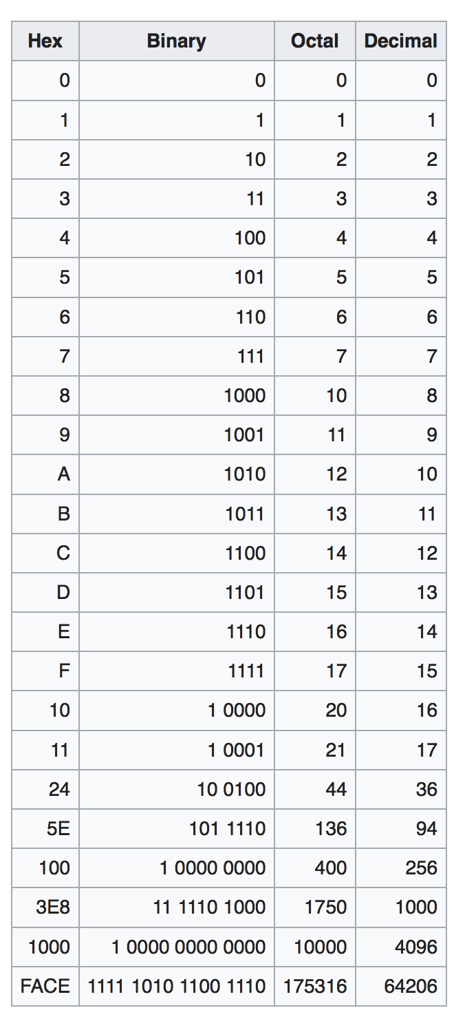
What if encoding in binary is too long on paper or text editor? We can use other number systems: encode in octal (base 8) or hex (base 16) to shorten its representation, so that it’s more “human friendly” to write.
See the table below to find out the direct conversion between binary, octal, hex, and decimal.
Don’t Worry!
After some practice, it should be easy to naturally guess the decimal value of any 4-bit number without computing them from scratch.
Prefix and Suffix
We typically use the prefix
0xto indicate that a number system is encoded in hexadecimal and not decimal. If we encode a number in binary, we can use the prefix0bor not at all based on context (because it is pretty obvious since a string of numbers only contain0s and1s). Numbers encoded in oct will have the suffix \(_8\).
The examples below should provide a straightforward hints on how to convert between the number systems.
Example 1
- Binary : 101 101 101 111
- Octal : \(5557_8\):
- To obtain this, group the binary digits into groups of 3 bits from right to left and convert them to its corresponding octal representation.
101 101 101 111:5557\(_8\)
- Decimal : 2927
- Hex:
0xB6F- To obtain this, group the binary into groups of 4 bits from right to left as well, and convert each group to its corresponding hex representation.
1011 0110 1111:0xB6F
Example 2
- Binary : 111 110 101
- Octal : \(765_8\)
- Decimal : 501
- Hex:
- Pad the higher bits of the binary so that the total number of bits is the closest divisible by 4. In this case, we expand from 9 bits to 12 bits by adding three
0s at the higher bits. Notice that this does not change the numerical value of the binary string. 111 110 101is equivalent to0001 1111 0101,hence0x1F5
- Pad the higher bits of the binary so that the total number of bits is the closest divisible by 4. In this case, we expand from 9 bits to 12 bits by adding three
Encoding
Definition
Encoding is the process of assigning representations to information. Strings of bits can mean some value of integers, but we can also assign a fixed representation to them. For example, given four choices
A,B,C, andD, we can assign two bits each to encode each choice:00,01,10,11if they are equally probable.
More precisely, it is called the fixed length encoding, that is used in practice when all choices \(x_i, i=1,...N\) are equally probable.
There also exist variable length encoding but we will not learn that in this course.
2’s complement, floating-point encoding, and character encoding are all examples of binary encoding systems for different purposes.
Character Encoding
Character encoding defines how characters (letters, symbols, etc.) are represented as binary numbers so that they can be processed and stored by computers. For example:
- ASCII (American Standard Code for Information Interchange):
- Encodes English characters in 7 bits (e.g.,
A→1000001). - Often stored in 8 bits (1 byte) for convenience (extra bit as padding).
- Encodes English characters in 7 bits (e.g.,
- ISO-8859-1 (Latin-1):
- Encodes 256 characters in 8 bits (1 byte).
- Includes Western European characters (e.g.,
é,ñ,ç).
- UTF-8:
- Encodes Unicode characters, which support nearly all languages.
- Uses variable-length encoding:
- 1 byte (8 bits): For ASCII-compatible characters (e.g.,
A,B). - Up to 4 bytes (32 bits): For complex scripts (e.g., Chinese, emoji).
- 1 byte (8 bits): For ASCII-compatible characters (e.g.,
- UTF-16:
- Encodes Unicode characters in 16 bits (2 bytes) for most characters.
- Supports other language alphabets like Russian and Korean.
- For characters outside the Basic Multilingual Plane, it uses 4 bytes (2 surrogate pairs).
We can create digital devices that are able to map (decode) given encoded information, perform computations based on the received information, and encode back the output so that the results can be interpreted by us (users) or other devices.

Number Encoding
Numbers are also encoded for storage and processing:
- Floating-Point Encoding:
- Encodes real numbers in a scientific-notation-like format (e.g., IEEE 754).
- This is out of syllabus, but you can check the appendix if you’re interested.
- Signed Number Encoding:
- 2’s complement is used to represent signed integers. More explanation below.
2’s Complement
Definition
2’s complement is a method of binary integer encoding used to represent both positive and negative integers. The most significant bit represents the sign (0 for positive, 1 for negative).
2’s complement is most common way computers encode signed integers because it simplifies arithmetic operations like addition, subtraction, and multiplication in binary.
Signed or unsigned?
You can’t tell whether a device supports signed or unsigned bits by looking at its output bits alone. To determine whether a machine is signed or unsigned, you need to check specific documentation or system properties related to the machine or software.
For example, in 4-bit representation of a number:
0101is a positive number: \(2^2 + 2^0 = 5\)1011is a negative number: \(-2^3 +2^1+ 2^0 = -8 + 2 + 1 = -5\)
Interpretation
In 2’s complement representation, a binary number N is evaluated using the following rule:
\[N = (\text{bit}_{n-1} \times -1 \times 2^{n-1} + \sum_{i=0}^{n-2} \text{bit}_i \times 2^i)\]where:
- \(n\) is the total number of bits
- The MSB \(2^{n-1}\) contributes to the negative weight if it is
1.
The size of the number (i.e., the total number of bits \(n\)) is critical to correctly identify the most significant bit (MSB) and interpret the value in 2’s complement.
Without knowing the bit-width (\(n\)), it’s impossible to determine whether the MSB indicates a negative value. For example, 1101 could be interpreted differently depending on its size:
- As a 4-bit number:
1101has the MSB as1, indicating it’s negative (-3). - As a 5-bit number:
01101has the MSB as0, indicating it’s positive (13).
The bit-width defines the range of representable values and ensures proper interpretation of the MSB’s role in determining the sign.
Method to Negate: 2’s Complementing
We can apply this method below (also called 2’s Complementing the number) to negate an integer:
- Step 1: Apply 1s complement, that is to invert all 0s into 1s and vice versa on the original binary number
- Step 2: Add 1 to the resulting number from Step 1
Example
Given the 4-bit representation of binary number 0011 = 3, suppose we want to negate it to be -3. We do the steps below:
- Step 1:
1100(1s complement) - Step 2:
1100 + 1 = 1101(add 1)
The value of the result of step 2 above is : \(-2^3 + 2^2 + 2^0 = -3\).
This method can be applied to either numbers: the positive or the negative, and it will yield its counterpart. For example, in 4-bit representation of number -5, we have 1011.
- Step 1:
0100(1s complement) - Step 2
0100 + 1 = 0101(add 1). This number is decimal 5.
The Byte Convention
Convention: 1 Byte is 8 Bit
The byte is a unit of digital information that consists of 8 bits.
Our system usually report storage amount (disk space, RAM, etc) in terms of bytes instead of bits. Historically, the byte (groups of 8 bits) is smallest addressable unit of memory in many computer architectures and therefore storage systems are typically reported in terms of bytes. A RAM of 1GB in size means that it can hold \(1 \times 8\) billion bits of data.
The prefix “Giga” means \(10^9\) in International Unit of Systems (SI), however when you plug in a 1GB RAM, your system might report it as 0.93GB instead. This is because in computing, Giga means \(1024^3 = 2^{30}\) bytes exactly instead of \(10^9\) bytes because we operate in base 2 instead of base 10 in SI. To avoid this confusion, there exist another set of prefixes: Kib, Mib, and Gib to denote \(1024\) bytes, \(1024^2\) bytes, and \(1024^3\) bytes in digital systems.
Introduction to Logic Gates
Logic Gates
Logic gates are basic electronic devices that perform Boolean logic operations, taking binary inputs (0s and 1s) and producing a single binary output. They form building blocks of digital circuits They are implemented using physical components such as transistors and diodes to process digital information in computing hardware. We’ll focus on the theory of logic gates first, while the details of transistors and hardware implementation will be covered later.
In the previous section, we learn how information is represented using binary form, characterized by sequences of 0s and 1s. These binary digits do more than just represent numerical values; they are fundamental to the operational logic of computers.
Each binary digit forms the basis for decision-making processes within digital circuits, where these 0s and 1s are interpreted not just as numbers but as discrete states—off or on, false or true. This binary decision-making is implemented through the use of logic gates, which manipulate these bits to perform all kinds of computational tasks, from basic arithmetic to complex algorithmic executions.
Understanding binary digits paves the way for understanding how computers process information, make decisions, and ultimately execute tasks.
Basic Boolean Logic Operations
Boolean operations form the core of digital logic, using simple rules to determine outputs from binary inputs. These operations are critical for understanding how logic gates manipulate data to perform computations. Below are the basic Boolean operations that are pivotal in digital electronics:
- AND: Returns true if all the inputs are true.
- OR: Returns true if at least one of the inputs is true.
- NOT: Returns the opposite of the input value.
- BUFFER: Passes the input directly to the output without any modification.
- XOR (Exclusive OR): Returns true if an odd number of inputs are true.
Each of these operations corresponds to a specific type of logic gate that we will explore next, demonstrating how theoretical Boolean logic is applied practically in hardware design.
Basic Types of Logic Gates
Every logic gate has one output terminal (Z). The number of input terminal can vary from 1 to N.
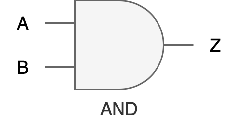
AND Gate
Function: Produces an output of 1 only if all its inputs are 1.
Input Terminals: 2 or more.
Truth Table:
| A | B | Z |
|---|---|---|
| 0 | 0 | 0 |
| 0 | 1 | 0 |
| 1 | 0 | 0 |
| 1 | 1 | 1 |
Digital Hardware Symbol:
Practical application in programming: in a while loop, an AND gate can be used to ensure that the loop continues to iterate only as long as all specified conditions remain true,
// C
while (conditionA && conditionB) {
    // logic
}

// Python
while (conditionA and conditionB):
   // logic
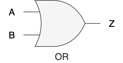
OR Gate
Function: Produces an output of 1 only if at least one of its inputs is 1.
Input Terminals: 2 or more.
Truth Table:
| A | B | Z |
|---|---|---|
| 0 | 0 | 0 |
| 0 | 1 | 1 |
| 1 | 0 | 1 |
| 1 | 1 | 1 |
Digital Hardware Symbol:
Practical application in programming: used to ensure that a certain block of code executes if any of the specified conditions are true,
if (condition1 || condition2) {
    // execute code
}
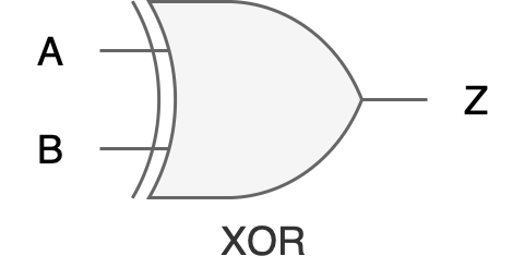
XOR Gate
Function: Produces an output of 1 when an odd number of inputs are 1.
Input Terminals: 2 or more.
Truth Table:
| A | B | Z |
|---|---|---|
| 0 | 0 | 0 |
| 0 | 1 | 1 |
| 1 | 0 | 1 |
| 1 | 1 | 0 |
Digital Hardware Symbol:
Practical application in programming: useful when you need to check for conditions that must be mutually exclusive, like scenarios such as setting toggles where one option disables the other,
if (condition1 ^ condition2) {
    // execute code if exactly one condition is true
}
NOT Gate (Inverter)
Function: Produces an output that is the inverse of the input. Input Terminals: exactly 1.
Truth Table:
| A | Z |
|---|---|
| 0 | 1 |
| 1 | 0 |
Digital Hardware Symbol:

Practical application in programming: an if statement where you want to execute code only if a condition is not met,
if (!condition) {
    // execute code if the condition is false
}
BUFFER Gate
Function: Outputs exactly what it receives as input; it acts as a repeater. Input Terminals: exactly 1.
Truth Table:
| A | Z |
|---|---|
| 0 | 0 |
| 1 | 1 |
Digital Hardware Symbol:

Practical application: Not obvious in programming, but A buffer gate in digital hardware level serves as a signal strengthener, essentially passing the input it receives directly to its output without alteration, but often with increased drive capability. This means it helps in maintaining the integrity of the signal through physically long circuits or across components that might degrade the signal due to resistance or other factors.
Combining Logic Gates
Understanding how these gates work individually is just the beginning. The next step is to see how they combine to perform complex operations and make decisions within digital circuits (and ultimately how to make a general purpose computers from billions of these gates). This knowledge is not only pivotal for building hardware but also enhances our ability to design efficient, programmable systems.
For example, let’s build a two-bit comparator that determines if one binary number \(A\) is greater than another \(B\) (only checking for greater than, not less than). Each binary number consists of two bits: \(A_1A_0\), and \(B_1B_0\). The comparator will produce a one bit output indicating whether A>B. If you were to write a program for this, you would write something like this:
def is_a_greater_than_b(A1, A0, B1, B0):
    # Check the most significant bits first
    if A1 and not B1:
        return True
    elif A1 == B1:
        # If most significant bits are equal, check the least significant bits
        if A0 and not B0:
            return True
        else:
            return False
    else:
        return False

# Example usage:
# Let's assume A = 10 (binary) and B = 01 (binary)
# A1 = 1, A0 = 0, B1 = 0, B0 = 1
result = is_a_greater_than_b(1, 0, 0, 1)
print("Is A > B?", result)
The logic of the function implemented in Python above can be translated into a hardware design using logic gates, which form the basis of a hardware comparator unit. In hardware, the function’s operations—comparing bits and determining the result based on their values—would be implemented using a combination of basic logic gates such as AND, OR, NOT, and XOR gates. Here’s a hardware design that implements is_a_greater_than_b function above:
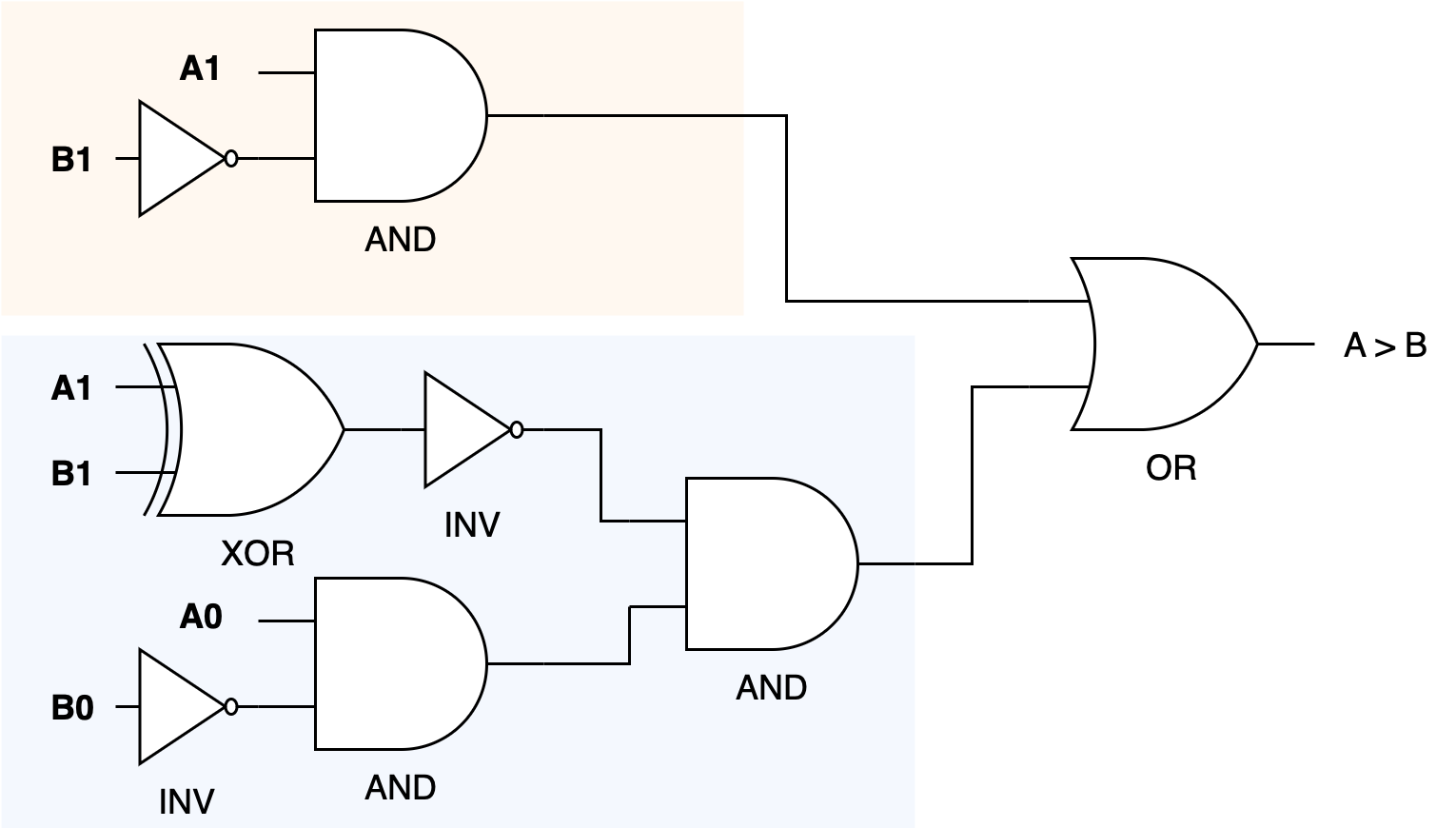
Explanation:
- Comparing Most Significant Bits (MSBs):
- AND Gate: Used to check if
A1is 1 andB1is 0 directly, mapping toA1 and not B1. - This result can directly influence the output if
Ais greater, bypassing the need to check the least significant bits (LSBs).
- AND Gate: Used to check if
- Equality Check:
- XNOR Gate: Typically, you might use an XNOR gate to compare
A1andB1to check for equality because XNOR outputs true when both inputs are equal. This can control whether to proceed to compare the LSBs.
- XNOR Gate: Typically, you might use an XNOR gate to compare
- Comparing Least Significant Bits (LSBs):
- AND Gate: Similar to the MSB comparison, another AND gate can be used for
A0 and not B0to check the condition when the MSBs are equal.
- AND Gate: Similar to the MSB comparison, another AND gate can be used for
- Overall Logic:
- OR Gate: If
A1 > B1or (if they are equal andA0 > B0, thenA > B. This can be implemented by feeding the outputs of the respective AND gates to an OR gate, whose output would then representA > B.
- OR Gate: If
- Final Output:
- The outputs of these gates would typically be connected to form the logic needed for the comparator. For
A == B, the output from an XNOR gate (checking both bits pairs) could be used directly, and forA < B, you could mirror theA > Blogic by swapping the inputs.
- The outputs of these gates would typically be connected to form the logic needed for the comparator. For
Example of Practical Application
In practical applications, such hardware comparators are used in sorting algorithms implemented in hardware, digital signal processing for real-time decision making, and anywhere within a digital system where two binary values need to be compared quickly and efficiently without the overhead of software computation.
For instance: automatic focus adjustment in digital cameras
- Multiple hardware comparators can be used to compare the sharpness levels (converted into binary values) of different focus settings in real-time.
- Each comparator evaluates pairs of sharpness values to determine which focus setting produces a clearer, sharper image.
- The use of hardware comparators allows this decision process to be almost instantaneous, which is essential for photography where lighting and scene conditions can change rapidly.
Abstraction: A General Purpose Computer
Logic gates form the bedrock upon which general-purpose computers are built, translating fundamental digital principles into versatile computing capabilities. By implementing basic operations like AND, OR, and NOT at the hardware level, these gates enable computers to perform complex calculations and decision-making processes efficiently.
This foundational hardware logic allows developers to abstract away from the physical electronics to focus on software development.
In practical terms, this means that instead of manually constructing circuits in a lab for specific tasks, programmers can write flexible and sophisticated Python code that the computer interprets and executes using its underlying logic gate-driven architecture. Thus, the intricate arrangement of logic gates in a computer’s hardware directly enables the high-level programming and software applications that drive modern technology. It bridges the gap between electronic design and software functionality.
A short appendix is provided for students interested in how probability and uncertainty relate to data representation and communication systems. This material is not required for the remainder of the course.
Summary
You may want to watch the post lecture videos here.
Here are the key points from this notes:
- Number Systems: Digital systems uses binary number system, but we touched on decimal, octal, and hexadecimal number systems for convenient representation.
- Encoding Methods: There exist fixed encoding and variable encoding methods, but we only touched on the former. Fixed encoding refers to a method of representing information, such as text, data, or signals, where a predefined, unchanging scheme is used to encode and decode the information (like ASCII and Unicode). This is useful so that we can consistently represent data across different systems.
- 2’s Complement: A way to encode signed integers. Signed integers are represented using 2’s complement (flip the bits then increment by 1), thus enabling the representation of negative numbers in binary form.
- Basic Logic Gates: Get familiar with basic logic operations like XOR, AND, OR, and INV. These basic logic gates are the basic building blocks for a more complex combinational circuit.
- Encoding data with \(X\) bits:
- We can represent \(2^X\) distinct values with \(X\) bits
- If it represent unsigned integers, it ranges from 0 to \(2^X-1\)
- If it represents signed integers, it ranges from \(-2^{X-1}\) to \(2^{X-1}-1\) (the range is divided between positive and negative values)
Next Steps
Finally, you might be wondering why are we counting the number of bits required to encode some amount of information, and why do we bother with encoding information in terms of bits at all.
As said in the introduction, the goal of this course is to learn how to build a general-purpose digital device (computers).
We begin the first half of our learning journey by trying to create a digital device (not for general purpose yet) that’s for a specific purpose, for example:
- a simple device that can perform N-bit addition (Lab 1: Combinational Logic With FPGA),
- a simple device that can perform basic logic computation: addition, subtraction, bitshift, boolean operation (Lab 3 & 4: ALU),
- a simple electronic game device that can take input from players, compute it, and determine the winner (1D Project)
Information as Voltage Values
Regardless of the specific purpose, we need a way to implement the logic (“addition” logic for example) for this machine. If we were to explain the workings of an adder to you, it will be pretty easy because we use the English language to communicate all the necessary information for you to understand how it works. Explaining this logic to a machine isn’t quite as easy because they don’t understand English – they only can comprehend “low” and “high” voltages.
Therefore we have to move the domain of which we convey information in terms of binary digits (bits), and get used to encoding logic (information) in this domain.
Once we are comfortable with conveying logic (information) in terms of bits, then we have to start finding components that can manipulate voltages, and this component is called a transistor – which you will learn pretty soon.
Problem Sets
The problem sets are created so that you’re comfortable with bit manipulation and communicating (with your future machine) in that domain.
Transistor is not the first tool created to manipulate voltages: triode vacuum tubes and electro-mechanical relays were used in pre-1950s. Before electricity was discovered, people used mechanical gears and punch cards to encode digital data. Also in case it’s not clear, digital data is the discrete, discontinuous representation of information.
Early Transistors
If you Google “triode vacuum tubes”, and “electro-mechanical relays” – or even the “early transistors”, you’d realise that they have quite a large size and they are definitely not cheap. You can find some information here for context, but on average in the past it costs about \(8\) each. They cost about a billion times more than they are now, so your computers that have billions of transistors might cost you a few billion $$ in the past (not to mention that it would’ve been enormous in size too).
It might be unimaginable how big and expensive computers were at first because we are so used to having portable computers – consisting of billions of cheap and extremely small transistors (5-7nm) and pretty much “unlimited” storage unit (we can always buy external drive, cloud storage, extend our RAM or simply buy computers with terabytes of disk size). But in the past – life wasn’t quite as easy.
With this in mind, it makes sense that if someone (in the past) were to make a digital device from scratch, he or she has to be mindful with the size and cost of the device, and therefore has to be mindful with counting (and probably minimising) how many bits are needed to contain all information and logic necessary for the intended device to work.
General Purpose Computers
But having a digital device that can do only that specific job: just addition, just that game logic, or just playing a VCD (VCD player) is not enough. We do not want to:
- Have so many devices to carry
- Spend so much money to buy 1 device for each task
- It will be ridiculous now to imagine if we need 1 separate, physical device for everything: 1 device to browse, 1 device for each video game, 1 device for chatting with a particular person, 1 device for computing addition, 1 device for computing division… you get the idea.
Therefore towards the middle of the term, we will learn how to create a better digital device: a programmable one that is suitable to be used for a plethora of purposes without any hardware changes – and can manipulate, store, and produce digital data.
We will consider all things necessary to create this programmable device that can tend to various general purposes (not just limited purposes) – meaning to create a device that can emulate the behavior of many other devices (given a description of how that other devices work: software), so that we simply just need to get this ONE device to perform many tasks and computations. This device is none other than our computers.
“Computers” include any device: your laptops, desktops, and smartphones, etc for which you can install and run various kinds of software.
Appendix
Practical Relevance of Information Theory
Expanding the practical relevance of information theory, let’s further explore how the foundational principles link to the applications of logic gates and their broader impacts on technology and digital systems.
Error Detection and Correction:
The principles of information theory are crucial in the design of error-correcting codes. These codes are fundamental for communication systems, where they ensure that data is transmitted accurately over noisy channels. Logic gates are integral in constructing these codes; for instance, XOR gates are often used in parity checks, which are a basic form of error detection. Engineers design circuits that automatically correct errors in data transmission, enhancing reliability in everything from satellite communications to internet traffic.
Data Compression:
Information theory provides the mathematical underpinnings for data compression techniques, which are essential for managing large datasets, streaming video, and optimizing storage. Compression algorithms, like Huffman coding or Lempel-Ziv, rely on the probabilities of data occurrences to reduce the number of bits required to represent the data. Logic gates in hardware accelerators perform these algorithms rapidly, supporting real-time data compression which is crucial for streaming services and telecommunication.
Optimizing Data Storage and Retrieval:
In the context of databases and memory systems, the ‘information content’ or entropy of data determines the most efficient ways to store and retrieve it. For example, databases use indexing mechanisms, which are optimized based on the expected frequency of query terms, directly applying principles from information theory. Logic gates are used to design the circuits in SSDs and RAM that manage data access and storage, ensuring quick retrieval and efficient space usage.
Digital Signal Processing (DSP):
Digital signal processors use various algorithms to manipulate signals such as audio, video, and other data inputs in real time. Information theory guides DSP algorithms to filter out noise and enhance signal integrity. Logic gates are employed in DSP chips to execute these algorithms efficiently, enabling applications like noise-canceling headphones and high-definition television.
Network Routing and Management:
Information theory also informs network routing algorithms that manage the flow of data across computer networks. Routing protocols use probabilities and information metrics to make decisions about the best paths for data packets to travel, optimizing network performance and reliability. The hardware that drives these decisions uses complex arrays of logic gates to process routing information dynamically.
Cryptography:
Cryptography relies heavily on information theory to secure data. Understanding the entropy of systems and their data helps in designing secure encryption protocols, where logic gates play a role in the actual encryption and decryption processes. For instance, XOR gates are a basic component in many encryption algorithms, including stream ciphers.
Conclusion
By linking the theoretical aspects of information theory with practical applications through logic gates, we see a direct impact on numerous technologies. These applications not only demonstrate the practical utility of theoretical knowledge but also underscore the importance of digital logic design in modern computing and electronic communication. This expansion into the practical relevance of information theory and logic gates reveals their profound interconnectedness and the pivotal role they play in the technological advancements that define our digital age.
Floating Point Encoding
Out of Syllabus
This section is not tested, and is simply written for completeness of knowledge only.
Definition
Floating-point encoding is a method used to represent real numbers in binary format, including very large or very small values, by breaking them into three main components: the sign, the exponent, and the mantissa (or significand)
Structure of Floating-Point Numbers
In the IEEE 754 standard, a floating-point number is encoded as:
- Sign (1 bit): Determines whether the number is positive (0) or negative (1). This is the MSB.
- Exponent (e bits): Encodes the scale or range of the number by specifying the power of 2 that the significand is multiplied by. You need to subtract it with bias of 127.
- In single floating point precision (32 bits total), e is 8
- Mantissa/Significand (m bits): Represents the precision or the significant digits of the number.
- In single-precision floating point precision (32 bits total), m is 23
For example, suppose we have
0 10000001 01110000000000000000000
Here we have:
- Sign:
0, it is a positive number - Exponent:
10000001(8 bits) - Mantissa:
01110000000000000000000
Exponent
Convert the value 10000001 to decimal, which is 129. Subtracted by bias of 127, we have 129-127=2.
What is a bias>
A bias is added to the exponent to allow it to represent both positive and negative powers of 2 while using unsigned integers.
For example: if an exponent is 129, it means “2”, if an exponent is 126, it means “-1”, and so on.
Mantissa
Definition
A mantissa represents the fractional part of the number, starting after the binary point.
Given the mantissa above, we first add the implicit 1 at the beginning (explanation given below, this is always done):
1.01110000000000000000000
Then we convert it to decimal value (follows the same logic as converting integer binary to decimal, just that with fractional power): \(1 + 0 * 2^{-1} + 1 * 2^{-2} +1 * 2^{-3} + 1 * 2^{-4} = 1.4375\)
Final Value
The final value can be computed as such:
\[Value = (-1)^{\text{sign}} \times 2^{\text{exponent}-\text{bias}} \times (1.\text{mantissa})\]The value for the example above will be \(2^2 * 1.4375 = 5.75\).
Normalised Numnber
Definiton
A normalized number in the context of floating-point representation is a number where the most significant digit (the digit to the left of the decimal or binary point) is non-zero.
In binary floating-point numbers, the number takes this form:
\[1.\text{fraction} \times 2^{\text{exponent}}\]Examples:
- 0.5 in decimal is \(2^{-1}\) in binary, which is written as \(0.1_2\)
- To normalize the number, shift the decimal point to the right by 1 position (basically until there’s only a single
1to the left of a point) and multiply with exponent that has fractional power - This results in \(0.1_2 = 1.0_2 \times 2^{-1}\)
- The normalized form is \(1.0_2 \times 2^{-1}\)
- The mantissa in single floating point precision is:
000 0000 0000 0000 0000 0000(23 bits)
- To normalize the number, shift the decimal point to the right by 1 position (basically until there’s only a single
- 10.38 in decimal is \(1010.0110_2\) in binary
- We shift the decimal point to the left until there’s only a single
1to the left of a point - This results in \(1010.0110_2 = 1.0100110_2 \times 2^3\)
- The normalized form is \(1.0100110_2 \times 2^3\)
- The mantissa in single floating point precision is
010 0110 0000 0000 0000 00001(23 bits)
- We shift the decimal point to the left until there’s only a single
Non-normalized Number
A non-normalized number does not require the leading digit to be 1. These numbers are typically used for very small values close to zero, where normalization is not possible because the exponent would become too negative. This number is smallest than the smallest normalized number.
The smallest normalized number would be when the exponent is 1: 0 0000 0001 0000 0000000000000000000
In decimal, this value is: \(1 \times 2^{-126} \times 1\), which is around \(10^{-38}\).
Floating Point Precisions
Floating-point precision refers to the accuracy and range with which real numbers can be represented in binary form. There are a few options:
| Precision Type | Bits | Significant Decimal Digits | Range Approximation |
|---|---|---|---|
| Half Precision | 16 | 3-4 | (6.1 \times 10^{-5}) to (6.5 \times 10^{4}) |
| Single Precision | 32 | 7 | (1.2 \times 10^{-38}) to (3.4 \times 10^{38}) |
| Double Precision | 64 | 15-16 | (2.2 \times 10^{-308}) to (1.8 \times 10^{308}) |
| Quadruple Precision | 128 | 34 | (3.4 \times 10^{-4932}) to (1.2 \times 10^{4932}) |
Choosing the right precision:
- Half Precision: Common in machine learning (e.g., GPUs) to save memory and increase speed for models tolerant of reduced precision.
- Single Precision: Used in graphics processing, gaming, and systems where moderate precision suffices.
- Double Precision: Standard for scientific, engineering, and financial computations requiring high accuracy.
- Quadruple Precision: Rarely used, but important for very high precision scientific simulations.
Information and uncertainty
After exploring the fundamental operations performed by logic gates, it’s crucial to understand how these elements contribute to the broader context of information processing in computing systems.
Information theory quantifies the amount of information in messages or events based on their probability. It provides a mathematical foundation for many aspects of computer science: data compression, error detection, and cryptography.
The amount of information held by an event is inversely proportional to the probability \(p\) of that event happening,
\[\begin{aligned} \text{Information } \propto \text{ Uncertainty} \propto \text{ }\frac{1}{p}.\end{aligned}\]Equivalently, the amount of information given is proportional to the uncertainty of that event happening. More precisely, to the logarithm of the uncertainty of the event happening. However since \(\log\) is an increasing function, the sense of proportionality remains the same.
In Layman Terms
If an event is bound to happen, then the fact that the event happens does not give any kind of information.
For discrete events \((x_1, x_2, ... , x_N)\) with probability of occurence of \((p_1, p_2, ..., p_N)\), the basic measure of information for all of these events is the bit.
The number of bits is needed to reveal that a random variable is \(x_i\) is:
\[\begin{aligned} I(X) = \log_2 \frac{1}{p_i} \text{ bits},\end{aligned}\]where \(I(X)\) is the amount of information received in bits learning that the choice was \(x_i\).
Equal Probability Events
Let \(N = 8\), and all 8 events are equally probable. The number of bits needed to encode all 8 events are:
\[\begin{aligned} I(X) &= \log_2 \frac{1}{1/8} = 3 \text{ bits}. \end{aligned}\]We need to receive 3 bits of information to learn that one event \(x_i\) out of the 8 events happens. In this case, it can be 000, 001, 010, 011, 100, 101, 110, and 111.
Narrowing Down Choices
With \(N\) equally probable choices, if it is narrowed down to \(M\) choices (where \(N>M\)), then we can say that we are given
\[\begin{aligned} I_{N\rightarrow M}(X) = \log_2 \left( \frac{N}{M} \right) \text{ bits}\end{aligned}\]Continuing from the example above, if our pool of possible events are narrowed down to 3 from 8, then intuitively we only need 2 bits (instead of 3) to encode 3 different events, e.g: 00, 01, and 10. Therefore we know we are given at least 1 bit of information.
With the formula above, N=8, M=3, therefore:
It is important to consider how the certainty or predictability of an event (or data set) influences how we can encode, transmit, and store it. The concepts of entropy and the logarithmic measure of information provide the theoretical underpinnings for many practical applications in computer science. Head to appendix for relevant practical examples if you’re interested.