- Seven Segment
50.002 Computation Structures
Information Systems Technology and Design
Singapore University of Technology and Design
Seven Segment
Project
The code used for this tutorial can be found here. We use the random number generator project to explain how seven segment unit (7seg) works.
Motivation
The seven segments is one of the most basic “display” unit you can use for your 1D project (the simplest one is just plain LED).
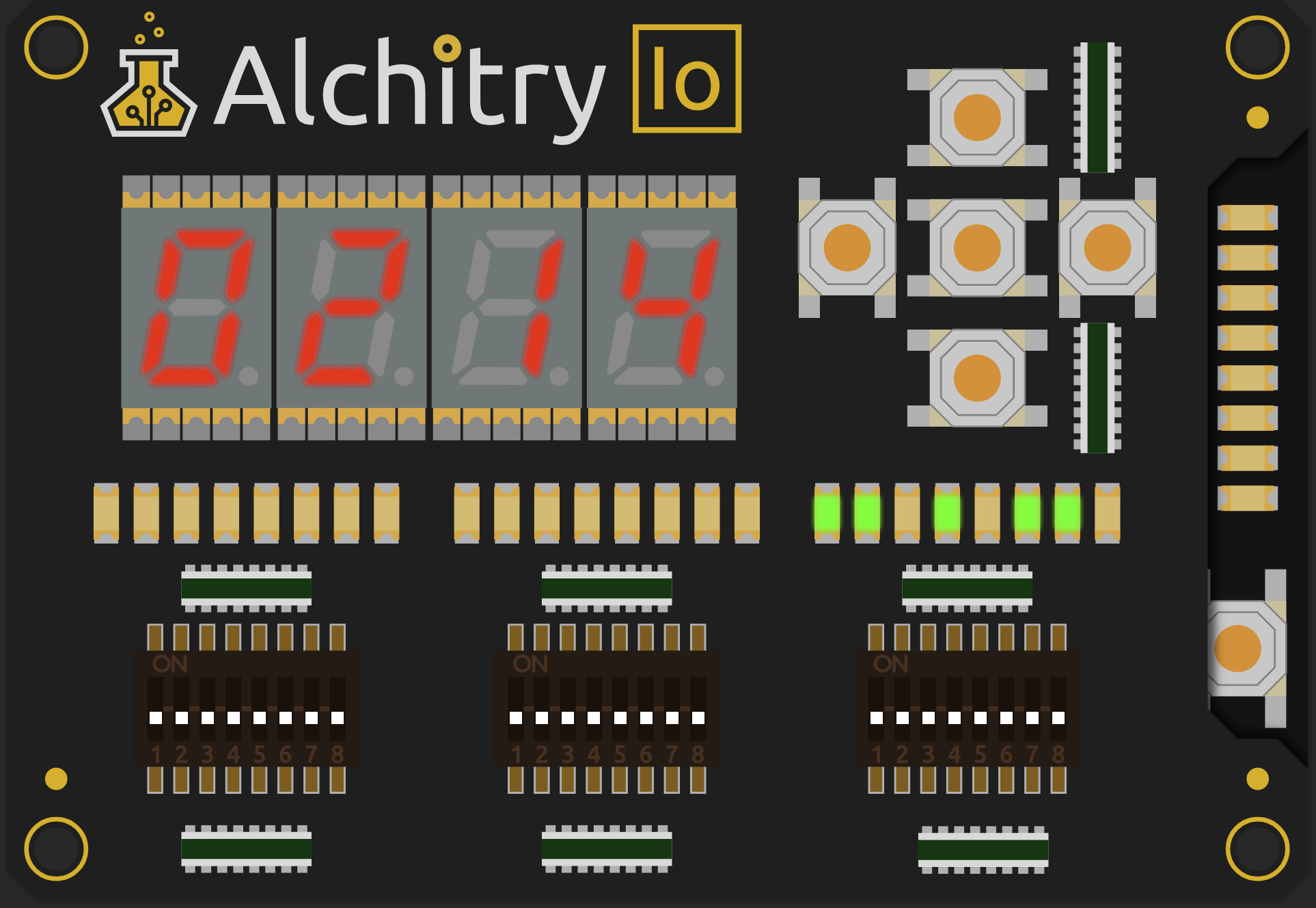
The 7seg unit that comes with Alchitry IO is a common anode unit, that is we use active low 0 to switch on the segment. The ports are named as the following in alchitry_top:
    output io_segment[8],   // 7seg LEDs on IO Shield
    output io_select[4],    // Digit select on IO Shield
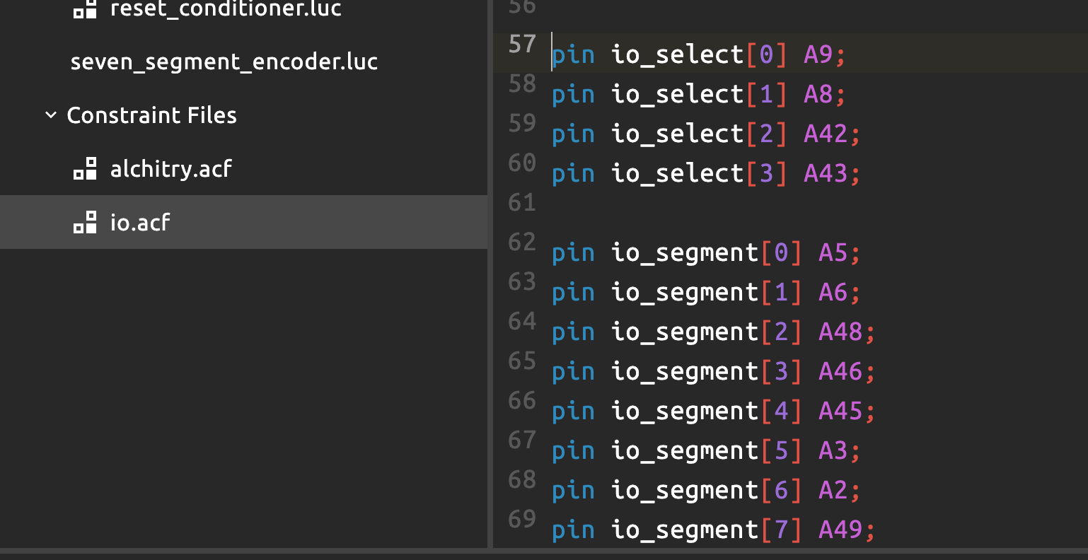
These ports are connected to the pins in the A bank, as defined in io.acf constraint file:
Seven Segment
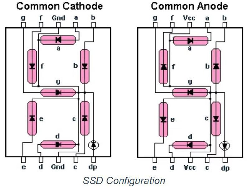
A seven-segment display is an electronic display device used to display numbers and some characters. It consists of seven LEDs (segments) arranged in the shape of a figure 8, with an optional additional LED for a decimal point.
Basic structure:
- Segments: Labeled as
a, b, c, d, e, f, g, each LED can be independently lit to form numbers or characters. - Common Connection:
- Common Cathode (CC): All cathodes are connected to a common ground. To turn on a segment: provide a
1(high voltage) - Common Anode (CA): All anodes are connected to a common power supply. To turn on a segment: provide a
0(low voltage)
- Common Cathode (CC): All cathodes are connected to a common ground. To turn on a segment: provide a
How to operate:
- To display a digit, specific segments are activated. For example, to display “1,” only segments
bandcare lit. - The display can show numbers (0–9) and some letters (e.g., A, b, C, d) as we lit up certain segments in the unit
It is widely used in digital clocks, calculators, meters, and other devices requiring numeric displays due to its simplicity and low cost.
Onboard 7segment: Common Cathode
The seven segment in your Io Element top is a Common Cathode 7 segment.
The Encoder
The file seven_segment_encoder.luc encodes the shapes 0 to E into 7 bits of value. Bit 0 to 6 (right to left) corresponds to segment a to g.
module seven_segment_encoder (
    input char[4],
    output segs[7]
  ) {

  always {
    case (char) {
      4h0: segs = 7b0111111;
      4h1: segs = 7b0000110;
      4h2: segs = 7b1011011;
      4h3: segs = 7b1001111;
      4h4: segs = 7b1100110;
      4h5: segs = 7b1101101;
      4h6: segs = 7b1111101;
      4h7: segs = 7b0000111;
      4h8: segs = 7b1111111;
      4h9: segs = 7b1100111;
      4hA: segs = 7b1110111;
      4hB: segs = 7b1111100;
      4hC: segs = 7b0111001;
      4hD: segs = 7b1011110;
      4hE: segs = 7b1111001;
      4hF: segs = 7b1110001;
      default: segs = 7b0000000;
    }
  }
}
For instance, the binary encoding of 7b0111111 corresponds to the segments lit up to form a 0 on a 7seg display. Only segment g is OFF, and hence bit 6 is 0.
There are actually 8 LEDS in the 7seg, the last LED being the decimal point (dp) but we typically don’t use that in 50002 projects since we don’t deal with floating point arithmetic.
The Segment Selector
In a 4-digit 7 segment, multiplexing is commonly used to reduce the number of pins required for driving the display.
Why multiplexing?
A single 7seg digit requires 7 segment pins (
atog) plus 1 or 2 more for the common pin (GND for cathode or VDD/VCC anode), so a 4-digit display would need 28+ pins if controlled individually. Multiplexing allows control of multiple digits using fewer pins by switching between them rapidly.
It typically uses a 1-hot encoding for selecting inputs or outputs in a 7seg display multiplexing setup. In 1-hot encoding, only one bit is set to 1 (active), while all others are 0. For a 4-digit CC display, we have a 4-bit digit select line with the following encoding:
- 1000 → Digit 1 is active.
- 0100 → Digit 2 is active.
- 0010 → Digit 3 is active.
- 0001 → Digit 4 is active.
Only one digit of 7segment can be active at a time.
For a 4-digit CA display, the opposite applies:
- 0111 → Digit 1 is active.
- 1011 → Digit 2 is active.
- 1101 → Digit 3 is active.
- 1110 → Digit 4 is active.
Pinout
The pinouts for common cathode and common anode are typically the same. The difference is to connect the common pin to GND (common cathode) or VDD (common anode)
Consult the documentation of your 7 segment to know the exact pinout. Some common single-digit arrangements are as follows:
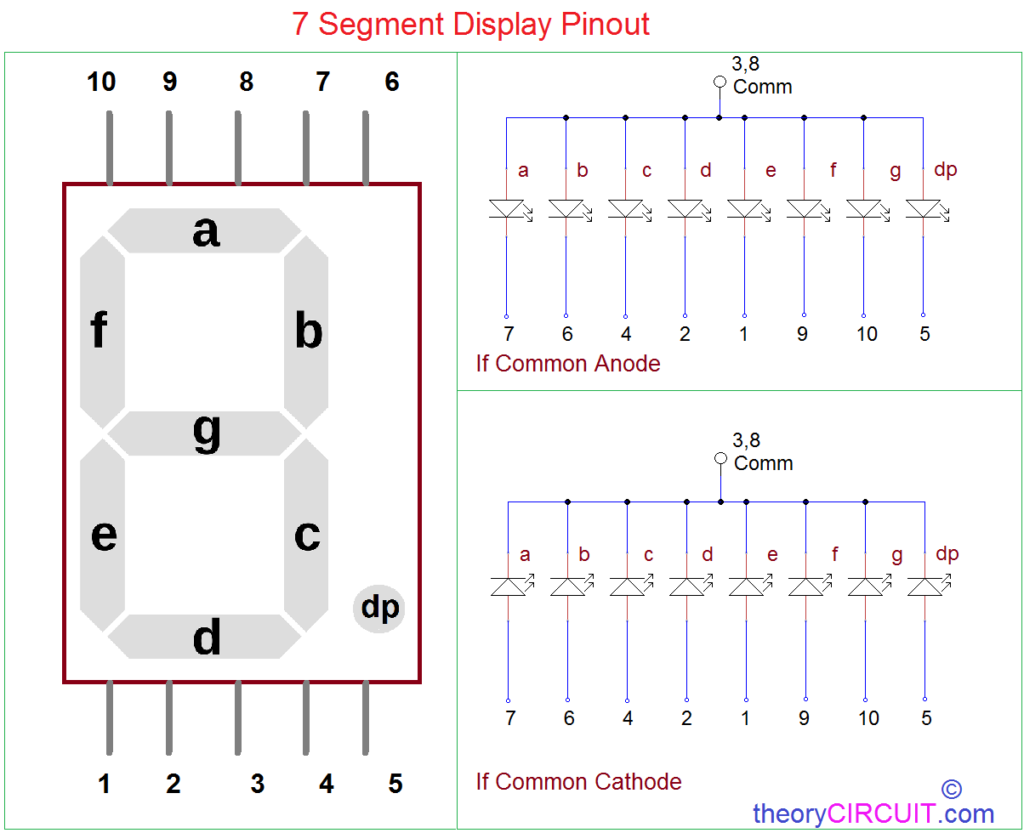
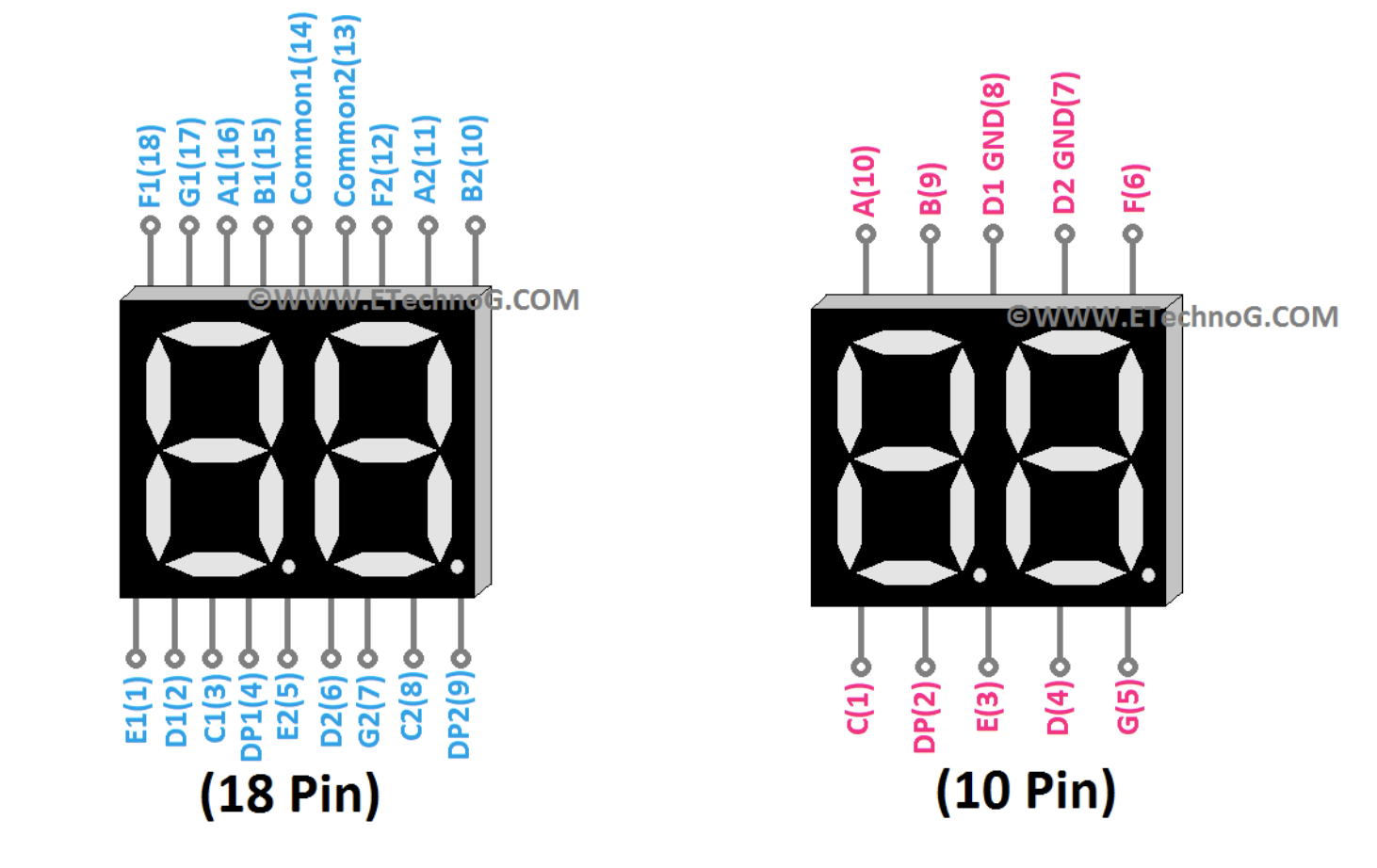
Double digit connections are commonly as follows (example below is common cathode, hence connected to GND. If it is a common anode, connect pins 8 and 7 to VDD):
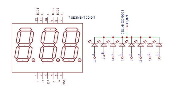
Three digit connections may be as follows (common cathode example):
And here’s a four-digit connection (common cathode example):
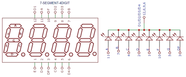
For segments with >1 digits, the digit selector is your common cathode/anode. This turn on just one digit:
- For common cathode: Drive one digit selector to LOW at a time, while the rest is set to HIGH.
- For common anode: Drive one digit selector to HIGH at a time, while the rest is set to LOW.
Implementation
In alchitry_top.luc, the ports io_segment[8] represents the segment control lines for the 7seg display while io_select[4] represents the digit select lines for the 4-digit display.
- Activate a Digit: Use
io_selectto enable one of the digits (e.g., setting io_select = 4’b0001 enables Digit 1). - Set the Segments: Use
io_segmentto specify which segments (a to g + dp) should light up for the active digit.
Generating io_select
We need to decide how rapidly we multiplex the display. This constant determines the multiplexing speed:
const SEG_REFRESH = $is_sim() ? 2 : 10
In simulation, since we have a 1000Hz clock and we set SEG_REFRESH to 2, we light up each segment for 0.004 second at a time (The divisor is 2 bits, thus resulting in frequency of \(1000/2^2\) = 250Hz).
We must generate the 4 4-bit selector signals: 1000, 0100, 0010, 0001, each set every 0.004 second. We use a decoder to produce the 1-hot encoding.
Decoder
A decoder is a combinational circuit that converts an n-bit binary input into \(2^n\) unique output lines, where only one output is active at a time.
These following components are created to produce io_select signal:
    .clk(clk){
        .rst(rst){
             dff seg_multiplex[2](#INIT(0))
             counter seg_clk(#SIZE(1), #DIV(SEG_REFRESH))
        }
        edge_detector seg_clk_edge(#RISE(1), #FALL(0), .in(seg_clk.value))
    }
    decoder seg_selector(#WIDTH(2), .in(seg_multiplex.q))
The following logic generates the input for the decoder:
        seg_multiplex.d = seg_multiplex.q

        if(seg_clk_edge.out){
                seg_multiplex.d = seg_multiplex.q + 1
        }
seg_multiplex.q will produce binary values 00, 01, 10, 11 in sequence (loops), and this serves as an input to the seg_selector decoder.
In summary:
- A counter (
seg_clk) runs at theSEG_REFRESHrate and triggers the edge detector (seg_clk_edge). - The dff (
seg_multiplex) cycles through the values00,01,10, and11(2-bit binary values), creating sequential inputs for the decoder (seg_selector). - The decoder converts these binary inputs to 1-hot encoded outputs (
1000,0100,0010,0001), which are used to activate the corresponding digit viaio_select.
Generating io_segment
Since the output of the random number generator (generator) is in binary, we need to first convert it to decimal. We use alchitry module bin_to_dec for this. The bin_to_dec module outputs 4 arrays of 4 bits. Each 4-bit represent a number from 0 to 9. For instance, if the input has a decimal value of 126 (1111110), the output will be {4b0, 0001, 0010, 0110}.
Afterwards, we pass the output of bin_to_dec module to the seven segment encoder to produce the 7 bit segment control lines.
    bin_to_dec bin_to_dec(#DIGITS(4), .value(generator.out), #LEADING_ZEROS(1))

    // match encoder[0].char to bin_to_dec.digits[0], and so on
    seven_segment_encoder encoder[4](.char($reverse(bin_to_dec.digits)))
Common Anode
Finally, since the io board 7seg is a CA 7seg, we need to invert the values going to io_segment and io_select:
        io_segment = ~encoder.segs[seg_multiplex.q]
        io_select = ~seg_selector.out
Hardware consideration of using 7 segment
In practice, each segment is an LED, so resistors are typically required to limit current and protect the LEDs. The 7segment that comes with alchitry_io already has resistors built into it. If you buy them for your project, you need to add resistors to each LED pin:
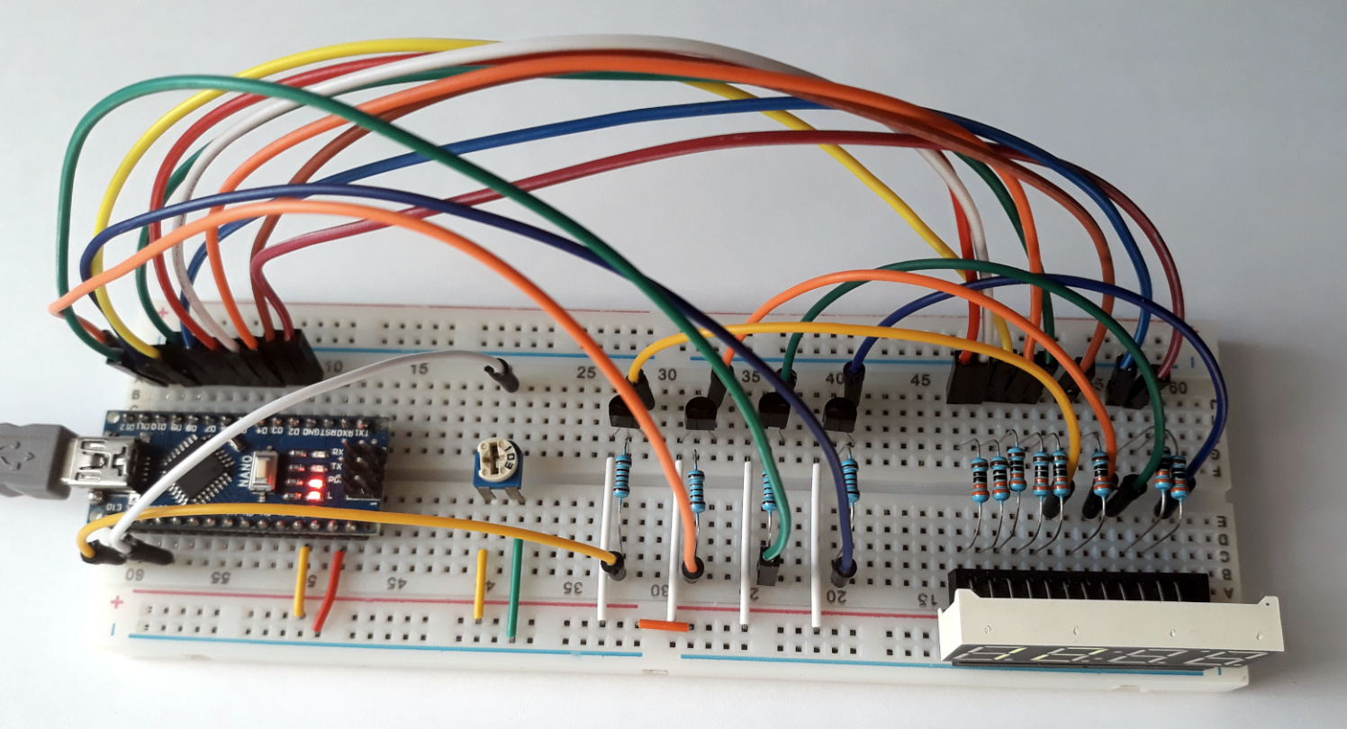
Please consider this in your design.
Consider also the amount of connections needed in your project. Suppose you need to use 5 units of 4-digit 7seg display (single colour). For a single 4-digit 7seg display, you typically have:
- 8 pins for segments (a-g + dp): Shared across all digits in the display.
- 4 pins for digit selection: One for each digit.
For 5 sch displays, you will need 60 pins and resistors in total (which is excessive).
Multiplexing strategy for multiple 7seg units
All should be of the same type (CC or CA)
All units ideally must be CC or CA. Do not mix. This way you can use a single common pin (GND for CC or VCC/VDD, the power supply, for CA).
Sharing segment lines
If you need to use this many 7 units, consider sharing segment lines across all displays.
- Use 8 pins (a-g + dp) to drive the segments for all displays.
- Connect all a pins from each 7seg digit/module together (solder), all b pins together, etc.
- Each display and its digits need separate control lines for digit selection.
For 5 displays, each with 4 digits, you will need 20 control lines (one per digit). This reduces your connection considerably from 60 to 28.
Resistor
Use resistors on all segment lines.
The value of the resistor can range depending on your usage, anything between 1-5 Kilo Ohm should work. You can consult AI on the exact resistor to use (detailed computation) if you wish. This is to protect the FPGA board. If you do not use resistors, too much current may be drawn, which may result in damaging the FPGA board.
Use decoder to support control lines
You can however use a decoder to further reduce the number of enable control lines.
For 20 digits, use a 4-to-16 decoder (requiring only 4 pins to control 16 digits) + 4 remaining control lines. In total, this further reduces your connection from 28 to 16 (plus 1 more connection of common ground or VDD depending on the type of the 7seg units).
74HC154/74LS154 (4-to-16 line decoder) is suitable for this purpose.
Cycle through digits rapidly
Move to the next digit quickly (e.g., every 1-2ms) to create the illusion of all digits being lit simultaneously. This shouldn’t be an issue since the onboard clk frequency is very fast (any value between 10 to 100Mhz is fast enough).
Summary
A 7segment unit is consisted of seven LED segments arranged in the shape of a figure 8, labeled as a through g, and an optional decimal point (dp). To use a 7seg display, you need to determine whether it is a common anode (CA) or common cathode (CC) type. Use active high (1) to light up segments in CC type, and use active low (0) to light up segments in CA type.
Each number or character is displayed by activating a certain combination of segments, which can be found in seven_segment_encoder.luc. Resistors are typically used in series with each segment to limit current and protect both the LEDs and the FPGA.
For multi-digit displays, multiplexing is used, where segments are shared across digits, and only one digit is activated at a time while rapidly cycling through all digits to create the illusion of simultaneous lighting.
Carefully plan your design for your 1D project. It is not recommended to make too many manual connections between the board and the hardware. Wherever possible, use a decoder.
 50.002 CS