 50.002 CS
- Overview
- Building a Virtual Processor
- OS Multiplexing and Context Switching
- Hardware Support for OS Multiplexing
- Synchronous Interrupt: Trap and Exception
- Summary
- Next Steps
- Appendix
50.002 Computation Structures
Information Systems Technology and Design
Singapore University of Technology and Design
Virtual Machine (Virtual Processor)
You can find the lecture video here. You can also click on each header to bring you to the section of the video covering the subtopic.
Detailed Learning Objectives
- Explain the Concept of a Virtual Processor
- Explain the operational model where each process perceives itself as operating on a dedicated machine.
- Discuss how this abstraction benefits multitasking and resource management.
- Describe the Role of the Operating System Kernel
- Argue the OS kernel’s role in process management and resource allocation.
- List out the kernel’s responsibilities in maintaining system security and process isolation.
- Explain Process Context and Isolation
- Define the components that make up a process context and their importance in the OS.
- Explain how the OS uses process context to maintain each process in isolation from others.
- Identify the Mechanisms Supporting Dual Mode Operation
- Describe the functions and importance of Kernel and User modes in operating systems.
- Discuss how these modes prevent unauthorized access and ensure system stability.
- Detail OS Multiplexing and Context Switching Techniques
- Explain how operating systems share hardware resources among processes.
- Describe the role of context switching and how asynchronous interrupts facilitate this process.
- Identify Hardware Requirements for OS Multiplexing
- Analyze the essential hardware features that support OS multiplexing.
- Discuss the mechanisms like interrupts and dual mode operation that ensure efficient process management.
- Conclude Synchronous and Asynchronous Interrupts
- Differentiate between synchronous and asynchronous interrupts and their roles in system operations.
- Describe how these interrupts interact with the OS to handle program execution and error management.
These learning objectives are designed to give a comprehensive understanding of how virtual machines function within operating systems, emphasizing the essential roles of the OS kernel and necessary hardware support.
Overview
The term “Virtual Machine” in this chapter does not refer to the regular commercial virtual machines like VirtualBox or VMWare Fusion.
Suppose we have 10 processes running in our computer right now: Web Browser, Spotify, Telegram, etc (in fact, the number of running processes at any given time in a typical computer is definitely more than 10 in day-to-day use, check your activity monitor or task manager to confirm).
There has to be some kind of manager program that oversees the execution of these processes because we only have limited amount of resources: CPU cores, RAM size, cache size, etc. This manager program is called the Operating System. Specifically, the part of the OS that is responsible for process management is the operating system kernel.
The role of the OS Kernel is to provide an environment such that each process is under the illusion that it has the whole machine (I/O devices, resources like CPU and RAM) to itself, while the truth is that we are actually sharing these hardware resources amongst many processes.
Virtual Machine (Virtual Processor)
A virtual processor is an abstraction provided by the operating system or hypervisor that allows a single physical processor core to emulate multiple independent execution contexts, enabling efficient multitasking or virtualization.
The Operating System Kernel
The Operating System (OS) Kernel is a special program that is written to manage and oversees the execution of all other processes in system. It has the highest privilege in computer system, i.e: it can terminate any program, has access to all kinds of hardware resources (Physical Memory, I/O devices).
A few of its important role include memory management, I/O handling, and process scheduling. There are many other roles of the OS Kernel that is not discussed here. We will learn more about them next term.
A Process Context
In the previous chapter, we learned that each process has its own VA to PAmapping we call as part of a process context, hence allowing it to run on its own virtual memory. Each process also needs to have its own context.
Definition
The term “process context” refers to the set of information that represents a process’s state at any given time, enabling the operating system to save and restore its state as needed, especially during a switch from one process to another.
Assigning a separate context for each process has two crucial benefits:
-
Allows timesharing among processes so that user can multitask even in a single-core system. It facilitates switching the execution of multiple programs in a single CPU core.
-
Allows each process to run in isolation. Every program can be written as if it has access to all memory and hardware resources, without considering where other programs reside.
The Kernel need to store more information about a process (and not just its VA to PA mapping), so that it can pause any given process and resume any of them later on without any conflict.
A more complete list of components that make up a process context are:
- Values of
R0, R1, ... R30 VAtoPAmapping- PC value
- Stack state
- Program (and shared code)
- Virtual I/O devices (console, etc)
In the Figure below, we illustrate N processes that are present in the system: P1, P2, ..., P3 – each having its own context:
These processes are isolated from one another, meaning that Pi cannot access (or corrupt) the memory space of other process Pj because each of them run on a separate virtual memory.

Writing a Kernel
Writing an Operating System Kernel is not a trivial task as one has to take into consideration a plethora of issues (security, performance, memory management, scheduling, etc). However with its presence, it makes easier to write all other programs.
Abstraction
An OS Kernel provides a layer of abstraction, allowing each program to run on a virtual machine, devoid of any knowledge and care about any other processes.
Building a Virtual Processor
Hardware Supported Kernel Mode and User Mode
To support a safe virtual machine for each process, we need to establish the notion of dual mode system, that is a system that has a Kernel Mode (privileged mode) and a User Mode (non-privileged mode):
-
The OS Kernel runs in full privilege mode called the Kernel Mode, and it’s code is made with the ability to oversee the execution of all processes in the computer system, handles real I/O devices, and emulate virtual I/O device for each process.
-
All other programs do not have such privileged features like the kernel. We call these programs as running in non-privileged mode called the User Mode with limited access to any hardware resources:
- No direct access to actual hardware
- No direct access other process’ address space
- No knowledge about other processes’ context and processor state
The Kernel will handle the need of these programs running in user mode for access to various hardware resources: access to I/O devices, interprocess communication, allocation/deallocation of shared memory space, etc.
This is a major benefit: programs can be easily written as if they have absolute access to all hardware resources (not just the physical memory), without having to worry about sharing them with other running processes.
OS Multiplexing and Context Switching
Multiplexing
Multiplexing is a method of sharing the resources in a computer system for multiple running programs at the same time. The OS kernel handles the multiplexed execution of various running programs in a single CPU – switching between contexts so rapidly – so that for the users, the computer is seemingly able to run multiple processes in “parallel”.
The main idea of OS multiplexing is illustrated below using two processes P1 and P2, sharing a single system:

The arrow illustrates the flow of execution in time:
- At first, the CPU runs some task from
P1. - After some time
t, imagine that a timed interrupt (caused by other asynchronous hardware, e.g: a timer) occurs. This causes the CPU to execute part of the kernel program that handles such asynchronous interrupt, hence pausing the execution ofP1. - The interrupt handler (part of the Kernel) takes control of the CPU when hardware interrupt occurs, and saves the current context (PC, Registers, etc) of P1 to a dedicated space (Kernel Stack) in the Memory Unit (so that P1’s progress is not lost and can be resumed later on) before performing a context switch.
- After the context switch is complete,
P2runs and progresses for some timetbefore another hardware interrupt occurs. The entire context switch process is repeated to pauseP2, resumeP1, and so forth.
Refer to appendix section if you’d like to know how this timer interrupt is set.
Note that some books might call a process’ context (PC, Registers, Stack, etc) as its state as well.
During context switch from P1 context to P2 context, two things should happen:
- The Kernel loads the context of
P2to the CPU (and also the required resources, mapping, etc), and - Resume the execution of
P2.
In practice, the interrupt handler will examine the cause of the asynchronous interrupt. In the event of periodic interrupt caused by a timer, the handler will delegate the task to the kernel scheduler whose job is to decide which process to run next, and prepare the necessary information and context to load this process back into the CPU so that the selected process may resume smoothly. When the scheduler returns to the handler, the handler resumes execution of the CPU by simply setting PC \(\leftarrow\) Reg[XP] - 4.
The key hardware that allows for OS Multiplexing is the asynchronous hardware interrupt. We will simply call asynchronous interrupt as just “interrupt” for simplicity. There also exist a synchronous interrupt which we call as “trap” instead (see the later chapters).
Async Interrupt
The term asynchronous comes from the fact that the interrupt will NOT be synchronised with the CPU clock. It can come at any moment. Inputs that causes these async interrupts include keyboard presses, mouse clicks, and scheduler’s timer. On the other hand, there are interrupts that are sychronous (with the CPU clock), for example faulty instructions will trigger a synchronous interrupt (trap). Unlike mouse clicks that can arrive at any time, execution of (faulty) instruction is synchronous with the CPU clock.
Hardware Support for OS Multiplexing
To allow for proper multiplexing, four things must be supported in the hardware level:
-
There has to be a way to asynchronously interrupt a currently running program periodically since that program is currently using the CPU and will not stop voluntarily. That means there has to be some kind of external timer system that will fire up an interrupt signal (to the Control Unit) when that current running process time quanta is up.
-
The hardware has to know how to direct the
PCto the right handler program when interrupt occurs. This address is hardwired toXAddrin our Beta. - Two execution modes must be supported in the system. In our Beta CPU, this mode is signified as
PC31.- Kernel mode: that allows the CPU to have ultimate access to all hardware and data, so that it can perform crucial process management tasks such as “saving” the states (Register contents, stack, PC, etc) of the interrupted process (to be resumed safely later on).
- User mode: a non-privileged mode that disallow programs to corrupt illegal memory space of other programs or hijack resources.
- Other interrupts must be disabled when the Kernel is saving the context (state) of an interrupted process (otherwise data will be lost).
\(\beta\) Asynchronous Interrupt Hardware
Recall the asynchronous interrupt datapath as shown in the figure below:
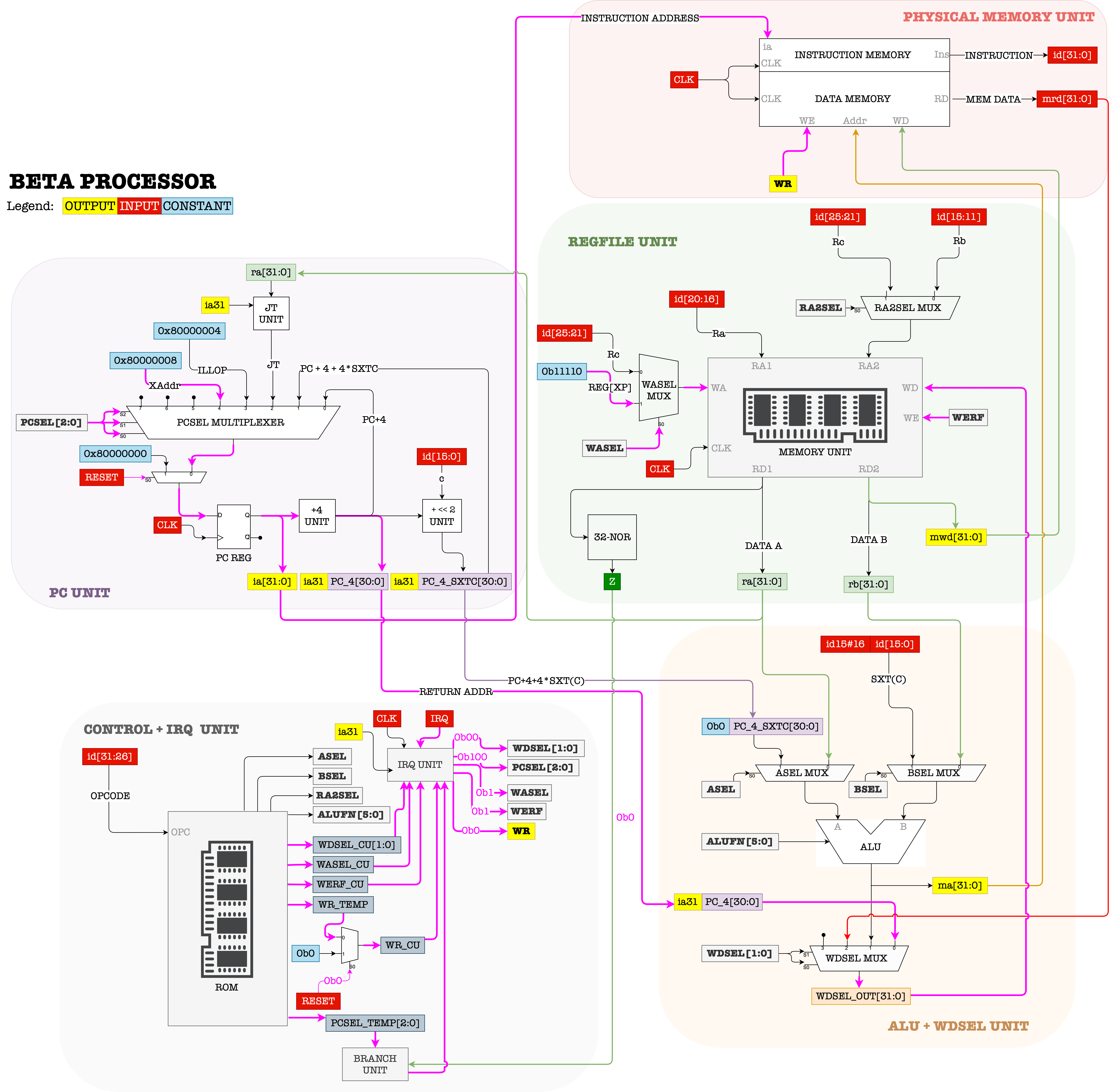
One of the inputs that is received by the Control Unit is IRQ (1-bit). In the event of asynchronous interrupt, that IRQ value will be 1. For instance, whenever a user clicks the mouse, or press a keyboard key, or the scheduler timer fires, IRQ will be set to 1.
Part of a Kernel program is a scheduler that will typically configure some system timer to fire at some interval. This timer runs asynchronously with the CPU, and sets the IRQ signal to 1 each time it fires.
At each CLK cycle, the Control Unit always checks whether IRQ is 1 or 0.
IRQis AsynchronousNote that
IRQmay turn to be1asynchronously, e.g: in the “middle” or even towards the end of a particular CPU CLK cycle. However the Control Unit is synchronised with CPU CLK. Therefore, this may only trigger an interrupt in the next CPU CLK tick. The exact implementation is hardware dependent, but here’s a general idea:
- If
IRQ==0, the Control Unit produces all control signals as dictated byOPCODEreceived.- Else if
IRQ==1, the Control Unit traps the PC onto the interrupt handler located atXAddr, by settingPCSELvalue into100; so that the PC points toXAddrin the next clock cycle.
- At the same time, it stores the address of the next instruction (
PC+4) at RegisterXP(R30).R30is a special register (also labeled as Reg XP) that is always used to hold the return address in the event of interrupt (or illegal operation) so that the system knows how to resume the interrupted program later on.
Beta’s interrupt hardware configuration forces the PC CPU to execute the interrupt handler at XAddr in the next cycle each time the timer fires.
The register transfer language that describes what happens in the datapath when IRQ==1 is:
If (IRQ==1 && PC31 == 0):
	Reg[XP] <- PC + 4`
	PC <- Xaddr
Asynchronous Interrupt Handler
The asynchronous interrupt handler is part of the Kernel’s code which ENTRY POINT must be located at XAddr, which is usually pre-determined memory address. In \(\beta\) CPU, XAddr is set at 0x8000 0008. Since XAddr is just one word of instruction, it is typically a BR to another address in memory that contains the instruction for the rest of the handler.
The first few instructions of the interrupt handler typically saves current process states (R0 to R30 contents, PC state, stack, and others) in the process table.
Process Table
Process Table
Process table: a Kernel data structure that stores all the states of running processes in the machine. It lives in the Kernel memory space. The kernel keeps track on which process is currently scheduled to run in the CPU.

Afterwards, the handler will figure out which specific service routine needs to be called to service the interrupt, e.g: scheduler, or I/O routines. Afterwards, the service routine returns back to this interrupt handler. The handler finally sets PC \(\leftarrow\) Reg[XP]-4.
Think!
What is the value of
Reg[XP]-4?
`Reg[XP]` contains the **next** address of the interrupted instruction. When we resume the interrupted process, we would like to re-execute this interrupted instruction. Hence, `Reg[XP]-4` **always** contains the address of that interrupted instruction that the CPU should execute when the interrupt handler returns.
Dual Mode Hardware Support
Since the OS Kernel is a program that manages the execution of all other processes in the system, it is crucial to restrict access to the Kernel for safety reasons. We need to prevent a normal program from jumping to the address in memory that contains Kernel code and compromise the system.
This prevention is done via hardware. The few sections below summarise how CPU hardware prevents access to restricted Kernel space (the memory region where the Kernel program resides).
PC31: Kernel and User Mode
Note that using PC31 as Kernel/User mode indicator is specific to Beta CPU. Other CPU architecture such as the x86 and ARM uses special registers (FLAGS register for x86 and CPSR for certain ARM architecture) for this purpose. The details about other CPU architecture is out of our syllabus, but the concept is similar.
Firstly, we need to establish some notion:
- We call the MSB (most significant bit) of the PC register as the Supervisor Bit.
- Whenever the PC executes any code in an address where its MSB is
1, it means that the CPU is running in the Kernel Mode. - Otherwise, if the MSB of the content in PC Register MSB is 0, the CPU is said to be running in the User Mode.
Kernel and User Space
With this convention of using the MSB of the PC as the status bit, we theoretically can divide the physical memory address space into two sections:
- User space: Addresses which MSB is
0: from0x0000 0000to0x7FFF FFFF - Kernel space: Addresses which MSB is
1: from0x8000 0000to0xFFFF FFFF.
Key Point
The split is a consequence of embedding the mode bit inside the PC, NOT a separately enforced policy. Any address above
0x7FFFFFFFis “kernel space” simply because executing code there would require PC31 = 1.
Kernel program and kernel data (privileged information, data structures, etc) can be safely stored in the kernel address space. The rest of the program in the system live in the user address space
Note that this is just an example. In other architectures, the MMUs can perform memory protection (protect certain regions) depending on the status bit, e.g: the MMU utilises the CSR (control status register) in RISC-V that contains the current privilege level and triggers a page fault if one tries to access illegal memory location.
User Mode Restrictions
The restrictions are illustrated using Beta CPU as example.
Restricted Branch
BEQ, BNE, and JMP in user mode cannot set PC31 from 0 to 1. Branch target computation for BEQ/BNE adds a signed offset to PC+4, and since PC31 = 0 in user mode, the resulting target will also have bit 31 = 0 unless the offset is large enough to overflow into the upper half, which the hardware does not allow because only exceptions set PC31.
JMP has an explicit rule: it can clear PC31 but never set it. The new PC31 is computed as old_PC31 AND JT31, where JT31 is bit 31 of the jump target register. So if PC31 is already 0, the result is always 0 regardless of the register value.
| old PC31 | JT31 | new PC31 |
|---|---|---|
| 0 | 0 | 0 |
| 0 | 1 | 0 |
| 1 | 0 | 0 |
| 1 | 1 | 1 |
A user-mode program loading 0x80000000 into a register and executing JMP to it will not enter kernel mode. The MSB will be masked off.
Restricted Memory Access (some)
Programs runing in user mode (PC31 == 0) should theoretically never load/store to data from/to the kernel address space. Computations of addresses in LD, LDR and ST should take this into account, but our plain Beta CPU datapath didn’t protect LD and ST.
The Beta ISA states that LDR computes its effective address relative to the current PC:
EA = (PC & 0x7FFFFFFF) + 4 + 4 * SEXT(literal)
PC31 is explicitly masked to zero before the addition. This means a LDR issued from supervisor mode (PC31 = 1) will always resolve into user space. The masking is intentional – LDR is designed to load constants placed near the instruction stream in user space, so it must ignore the mode bit.
However, LD and ST compute their effective address as follows without any protection:
EA = Reg[Ra] + SEXT(literal)
There is no masking of any bit in this computation. The full 32-bit result of the addition is used as the memory address. The Beta spec defines no hardware check on whether EA falls in user space or kernel space.
This means a user-mode program can construct an EA with bit 31 set and issue LD or ST to it. For example:
| CMOVE(0x8000, R1)      | R1 = 0x00008000             |
| SHLC(R1, 16, R1)       | R1 = 0x80000000             |
| LD(R1, 0x10, R2)       | EA = 0x80000010, no fault   |
| ST(R3, 0x10, R1)       | EA = 0x80000010, no fault   |
From the CPU’s perspective, both accesses go through to memory without any mode check. Nothing in the plain Beta datapath stops this.
In short, The Beta address space split enforces kernel isolation only for control flow. A user program cannot execute kernel code because it cannot set PC31. However, it can freely read and write kernel memory addresses through LD/ST if it constructs the right EA. In a real system, this would allow a user program to corrupt the kernel’s data structures, process table, or interrupt handlers.
MMU is needed to protect Kernel data.
Since the Beta spec explicitly leaves LD/ST memory protection as implementation-defined. The correct way to close this gap in a real implementation is a Memory Management Unit (MMU):
CPU --> MMU --> Physical Memory
         |
    checks EA against
    page table entries
    (user/supervisor bit,
     read/write permissions)
         |
    raises fault if
    user-mode EA hits
    kernel page
On each LD/ST, the MMU intercepts the EA, looks up the page table entry for that address, and checks whether the current privilege mode (from PC31 or equivalent) is permitted to access that page. If not, it raises a page fault, which traps into the kernel’s fault handler (ILLOP). The kernel then terminates the offending process.
Without an MMU, the Beta as specified provides execution isolation only, that is: user code cannot run in kernel mode, but it can still read and write kernel memory addresses directly through data memory instructions.
Restricted Kernel Mode Entry
Entry to the kernel mode can only be done via restricted entry points. In \(\beta\), there are only three entry points:
- Interrupts (setting PC to
Xaddr: 0x8000 0008), - Illegal operations (setting PC to
ILLOP: 0x8000 0004), or - Reset (setting PC to
RESET: 0x8000 0000)
We may also assume that we will never use the entire 32-bit address space for the \(\beta\) CPU, therefore we can utilise its MSB as a “status” flag. However, we lose the address “space” protection. Suppose we place Kernel code at address 0x00ABCC00. There’s nothing that can stop a user program from branching directly to this address (unlike if we place the kernel code at address 0x80ABCC00). This is just one of the consequences of using PC31 as the CPU status. There has to be other additional hardware unit in place to protect the kernel space in the RAM.
Summary
This table summarizes all the points above:
| Attempted action from user mode | Protected? | Mechanism |
|---|---|---|
| Branch/JMP into kernel space | Yes | PC31 cannot be set by branch or JMP |
| Execute kernel instructions | Yes | PC31 stays 0; kernel code unreachable |
LD from kernel address |
No | No EA masking in LD |
ST to kernel address |
No | No EA masking in ST |
LDR resolving into kernel space |
Partially | PC31 masked in EA calc, but only protects against accidentally landing in kernel space from supervisor-mode LDR |
| Entering kernel mode voluntarily | Yes | Only exceptions set PC31 |
Full LD/ST protection requires an MMU with page-level access control.
Synchronous Interrupt: Trap and Exception
Both Trap and Exception falls under synchronous interrupt category. This is a situation when the CPU executes a faulty instruction. This include illegal operations (instructions with OPCODE that doesn’t correspond to the ISA), and exceptions: division by zero, invalid memory access, invalid transfer of control (BR/JMP).
Executing any of these faulty instructions caused any process running in user mode to trap itself into the kernel mode because the PC will be directed to execute the trap handler (e.g: PC \(\leftarrow\) ILLOP). This handler is part of the Kernel code, and it will examine the cause of the trap. It will also perform the appropriate action that will “handle” this faulty event: e.g: crash (terminate) the calling process or other services.
Trap
Definition
A user process may intentionally execute an illegal instruction to trap itself to the kernel mode and gain access to its services. This is also known as making a Supervisor Call or a System Call. Control to the trap-calling process will be return after the requested service is completed. We will learn more about this next term.
I/O devices are actually shared among all processes in the system, but their programs are written with complete disregard for other processes in the memory. Therefore, user processes may utilise traps to synchronously interrupt themselves, and legally switch to the Kernel mode whenever they need access to the I/O devices (or other kernel services).
User processes do not have privileged access, meaning that they do not directly control the use of any hardware (I/O) devices, such as getting keyboard input, mouse click, perform disk saves, etc. It needs to trap itself to the Kernel program and execute specific parts of the Kernel code to obtain access to these I/O devices.
As said above, the event of transferring control of the CPU to OS Kernel synchronously / voluntarily when a process needs Kernel’s services is known as the system call (a.k.a: SVC, or supervisor call). This can be done by leaving the index of the requested service at Reg[R0] and executing a specific illegal operation (an instruction with OPCODE not corresponding to any other instruction in the ISA). In bsim, this OPCODE is chosen to be 1.
There are many types of Kernel services, one of them includes read/write access from/to the I/O devices. They are typically indexed, and the process needs to leave the index of the needed system call in Reg[R0] before trapping itself to the Kernel Program.
The datapath in the event of illegal operation is:

During this event,
- Control unit sets
PCSEL = 011, and savesPC+4intoReg[XP] - The PC will execute the instruction at location
ILLOPin the next cycle where the illegal operation handler resides. - The illop handler will look at
Reg[R0]and invoke the right service routine to provide the requested service.- Upon returning, the service routine will put its return the result in
Reg[R0].
- Upon returning, the service routine will put its return the result in
- The illop handler resumes the execution of the originating process:
JMP[XP]
There’s no need to do Reg[XP] = Reg[XP]-4 because we don’t wish to re-invoke the Trap / SVC when we return to the calling process.
Trap Example
One common scenario where a process running in user mode needs the Kernel service is when it asks for keyboard / mouse input, for example:
int c;
c = getchar();
printf("%s", c);
The function getchar contains several instructions that perform a supervisor call in order to fetch any character input from the keyboard. When translated into assembly, the supervisor call is made by trapping the process into the illop handler, thus transferring CPU control to the Kernel so that it can fetch any character input from the keyboard. The process execution can be resumed only after the getchar task is done. That is why we notice that our process “hangs” (didn’t execute the next print line until a user entered an input with a return carriage).
Finally, this C process stores the character input left at Reg[R0] by the Kernel into memory location c.
Exceptions
The details about exceptions are out of this syllabus, and you will learn more about this next term. The major difference between Exceptions and Trap is that Exceptions are caused by truly faulty instructions and the program causing these exceptions are typically terminated by the Kernel. We commonly understand this phenomenon as “crashing” programs.
Summary
You may want to watch the post lecture videos here.
Virtual machine is a crucial concept in modern computing, allowing multiple processes to run simultaneously on a single CPU. This is achieved through a combination of hardware and software optimizations, including the use of a virtual processor for each process. The operating system kernel plays a pivotal role in this setup, managing resources, ensuring security, and maintaining process isolation. Advanced hardware support, such as dual mode operation and specialized interrupt handling, further enables the efficient multiplexing of resources and smooth context switching. This not only enhances system stability and performance but also ensures that applications run seamlessly without interfering with each other.
This chapter covers various aspects of how operating systems manage multiple processes using virtualization technology, in particular: how the presence of OS Kernel and hardware support provide an abstraction for each running process, thus allowing them to run in an isolated manner; on their own virtual machine. Here are the key points from this notes:
- Concept of a Virtual Processor: The kernel supports process isolation. Each process operates as if it has its own dedicated hardware without having to interfere with one another by default.
- Operating System Kernel: The kernel plays a critical role in managing resources, ensuring security, and isolating processes.
- Process Context and Isolation: A process context is a data structure that allows processes to operate independently and securely. It refers to the complete state of a process at a given time, including its program counter, registers, memory mappings, and system resources, which the operating system saves and restores during context switching.
- Dual Mode Operation: Dual-mode operation is a system design where a processor operates in two distinct modes, typically user mode for executing user applications with limited privileges and kernel mode for executing critical operating system tasks with full access to hardware, ensuring security and stability. This is to ensure distinct access control.
- OS Multiplexing: The operating system’s ability to share resources (such as the CPU, memory, or I/O devices) among multiple processes or users by dividing time or space effectively, enabling concurrent execution and efficient utilization of system resources.
- Context Switching: A process by which the operating system saves the state of a currently running process and loads the state of another process, allowing multiple processes to share the CPU and ensuring multitasking in a time-shared environment.
- Transferring Control to Kernel: The Kernel manages the execution of all processes, as well as all I/O devices, and provides services to all these processes. When the CPU is running in user mode, there are two ways to transfer CPU control to Kernel program (kernel mode):
- Via asynchronous interrupt:
IRQis set to1 - Via synchronous interrupt: when the process generates an exception hence trapping itself to the handler and enters Kernel mode.
- Via asynchronous interrupt:
During either case of interrupt, PC+4 is stored at Reg[XP] so that the CPU knows how to resume the interrupted process later on once the interrupt handler returns.
Next Steps
We have the source code of a simple \(\beta\) CPU Kernel called the TinyOS. You will encounter this in 50005. Since it is a simple kernel, this kernel is non-reentrant (the CPU cannot be interrupted while in Kernel Mode). In practice, most modern UNIX Kernels are reentrant. Careful writing and construction of a reentrant Kernel program is required.
A reentrant kernel ensures that multiple processes or threads can safely enter and execute kernel code simultaneously without conflicts. It achieves this by avoiding global state modification, using per-process data structures, employing synchronization mechanisms like locks or semaphores, and ensuring that shared resources are accessed atomically or in a thread-safe manner.
Appendix
Timer Interrupt
The kernel uses a hardware timer to enforce context switches, ensuring that no single process monopolizes the CPU, thus allowing for efficient multitasking and fair CPU time distribution among all processes. Here’s how this is typically set up and managed:
Setting the Timer for Context Switches:
-
Timer Configuration: The kernel configures a hardware timer to generate an interrupt at regular intervals. This interval is often referred to as the “time slice” or “quantum”. The duration of this time slice can vary depending on the scheduling policy of the operating system.
-
Timer Interrupt: When the timer interval expires, the hardware timer generates an interrupt that is handled by the CPU.
-
Interrupt Service Routine (ISR): This interrupt triggers an Interrupt Service Routine (ISR) managed by the kernel. The ISR is a special function within the kernel that responds to the timer interrupt.
-
Context Switch: During the ISR, the kernel performs several tasks, including saving the state (context) of the currently running process and determining which process to run next based on the scheduling algorithm. The kernel then loads the context of the next process to be executed, effectively performing a context switch.
-
Resuming Execution: After the context switch, the newly selected process begins or resumes execution, using the CPU until the next timer interrupt occurs or until the process voluntarily relinquishes the CPU (e.g., waiting for I/O operations to complete).
Placement and Types of Timers:
-
Hardware Timer: The timer used for context switching is a physical hardware timer on the computer’s motherboard or integrated into the CPU itself. Common types include programmable interval timers (PIT), high precision event timers (HPET), and advanced programmable interrupt controllers (APIC).
-
Dedicated Timer Chips: Some systems may use dedicated timer chips like the Intel 8253 or 8254, which have historically been used in PC architectures.
-
System-on-Chip (SoC) Timers: In more integrated systems, such as those in embedded devices or modern PCs and servers, timers might be part of the SoC alongside the CPU, memory controllers, and other peripherals.
This hardware timer is crucial because it ensures that the operating system maintains control over the CPU and can enforce its scheduling policies, keeping the system responsive and stable by preventing any single process from running too long without interruption.
An example with Beta CPU
As mentioned above, to support timesharing, there has to be some sort of mechanism that will periodically interrupts the execution of an ongoing process so that another process can be swapped in. For instance, if we have a single core CPU and two running processes P1 and P2, we would like to run P1 for n clock cycles, and then pausing it. Afterwards, the Kernel scheduler will run P2 for another n clock cycles before pausing P2 as well and resume the execution of P1. This round robin scheduling will be repeated until one of the processes terminate. If n is small and the CPU clock frequency is large enough, there will be the illusion that P1 and P2 (to the eyes of the user) runs in the single core CPU simultaneously.
Rapid context switching between P1 and P2 gives the illusion of parallel execution. This phenomenon is called concurrency.
In this section, we illustrate an example of how a basic Kernel Scheduler works with the support of the timer hardware. A timer is commonly implmented as an M-bit counter (a separate hardware unit) with frequency of Y Hz that runs asynchronously with the CPU. This counter will be used as a timer for process scheduling. For example, suppose we have a 16-bit counter with frequency of 50Hz. This timer is connected to the IRQ line of the CPU.
The Kernel typically can set the IRQ signal to point to the any arbitrary bit of the counter (but we need more hardware to “clean” this counter signal, read below).
IRQ
There’s one more detail: we can’t let the
IRQsignal to always point to thenth bit of the counter because it will causeIRQto be1for more than 1 CPU clock cycle.Let’s use an example: suppose we have a CPU running on 100Hz clock, and a timer with 50Hz clock (so the timer is asynchronous of the CPU), and we select the
IRQto always point to the 5th bit of the timer. This 5th bit of the timer will alternate between0and1every 16 cycles (or 0.32s).This means that the IRQ signal will be
1for the first time after 16 cycles of the timer clock (0.32s), and it will remain1for another 0.32s before turning0. We do not what IRQ signal for 0.32s, that’s 32 cycles of the CPU clock! We only want it to be1just ONCE, exactly just for 1 cycle of the CPU clock. As a result, we need to pass the 5th bit of the timer into a rising edge detector driven with the CPU clock before connecting it to theIRQline of the CPU.
With the rising edge detector, it means that the IRQ value will be 1 once every 0.64 seconds.
If at first the CPU is executing instructions of Program P1:
- After 0.64 seconds,
IRQturns to1. This triggers an interrupt, and the control signals will cause the PC will execute the interrupt handler instruction atXAddrin the next cycle (and saving the supposed next instruction atReg[XP]). - The handler at
XAddrmust save register states, branch to the scheduler, and resume the program after the scheduler returns. Note thatReg[XP]may or may not be the same as when beforeBR(scheduler_handler, LP)is executed.
X_addr : ST(R0, save_location) || save register states at an allocated address
ST(R1, save_location+4)
ST(R2, save_location+8)
ST(R3, save_location+12)
....
ST(R30, save_location+30*4)

CMOVE(kstack, SP) || use kernel stack
BR(scheduler_handler, LP) || branch to the scheduler

|| return instruction from scheduler
LD(save_location,R0) ||  restore register states
LD(save_location+4,R1)
...
LD(save_location+30*4, R30)

SUBC(XP, 4, XP) || Reduce XP by 4 to re-execute the instruction that was interrupted by the timer
JMP(XP)  || Resume execution
Although not written, save_location is a label, representing an address to store P1’s states.
Observation
In this simple example, the handler is written such that it always branches to the scheduler. In practice, there are many kinds of hardware interrupts (not just from a timer) that needs to be handled differently depending on its type. We will have a hands-on experience about this in Lab 8, and also in the next term.
Reentrancy
When the CPU is in the kernel mode (PC31 == 1), i.e: handling an interrupt, it is important to consider whether or not we should allow more interrupts to occur.
Handlers which are interruptible are said to be re-entrant.
\(\beta\) CPU’s handlers are set to be non re-entrant. Interrupts are disabled when it is in kernel mode and IRQ signal is ignored in the hardware when PC31 == 1.
This means that while user programs are interruptible, kernel programs are not. The reason behind disabling interrupt while being in the Kernel mode is to prevent the Kernel from corrupting itself.
Why?
Consider the scenario where the interrupt handler is in the middle of saving program states. Allowing another interrupt to occur in the middle of a save might cause data loss (corruption).
The drawback to an uninterruptible kernel is that there’s no way to get the system to work again if the kernel is buggy and runs into an infinite loop, except via hard reset. The kernel program has to be written very carefully so as not to contain such bugs. In practice, kernel bugs exists and we often know this as kernel panic or the blue screen of death.