 50.002 CS
50.002 Computation Structures
Information Systems Technology and Design
Singapore University of Technology and Design
Relaxing Cross Clock Paths in Vivado
When a design has two clock domains running at different frequencies, and a signal crosses from the slow domain into the fast domain, Vivado (and other STA tools) will by default try to close timing using the tightest possible pair of launch and capture edges it can find between the two clocks.
For example, suppose a slow clock at 10 MHz (100 ns period) drives a register that feeds combinational logic into a second register clocked by a fast clock at 100 MHz (10 ns period).
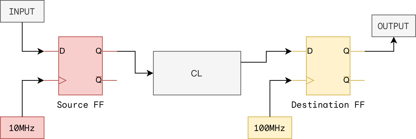
The static timing analyser enumerates all the edge pairings between the two clocks and picks the worst case, see region A and B below. That worst case is usually only a few nanoseconds, possibly far less than either clock period (region B), because at some point a slow clock rising edge will land just before a fast clock rising edge.
The tool then demands that the entire combinational datapath between the two registers settle within those few nanoseconds. If the path has any real logic in it, timing fails, even though physically the signal is stable for the full 100 ns slow clock period and has no trouble settling.
Symptoms of this problem:
- Setup violations with very large negative slack on cross clock paths
- Worst Negative Slack reports pointing at paths that “should” have plenty of time
- The path passes timing the moment you artificially slow the fast clock, which confirms it is an edge pairing issue and not a real logic delay problem
Attempt 1: Use set_multicycle_path
The textbook answer (or AI answer on the first few tries) for a signal that is stable for more than one destination clock cycle is set_multicycle_path, but this would fail. The intuitive version looks like this:
set_multicycle_path -from [get_clocks slow_clk] -to [get_clocks fast_clk] -setup 10
set_multicycle_path -from [get_clocks slow_clk] -to [get_clocks fast_clk] -hold  0
The setup line says “give the path 10 fast clock cycles to settle instead of 1.” That part is fine. The hold line is where it falls apart for cross clock multicycle. Let’s understand that with this example:
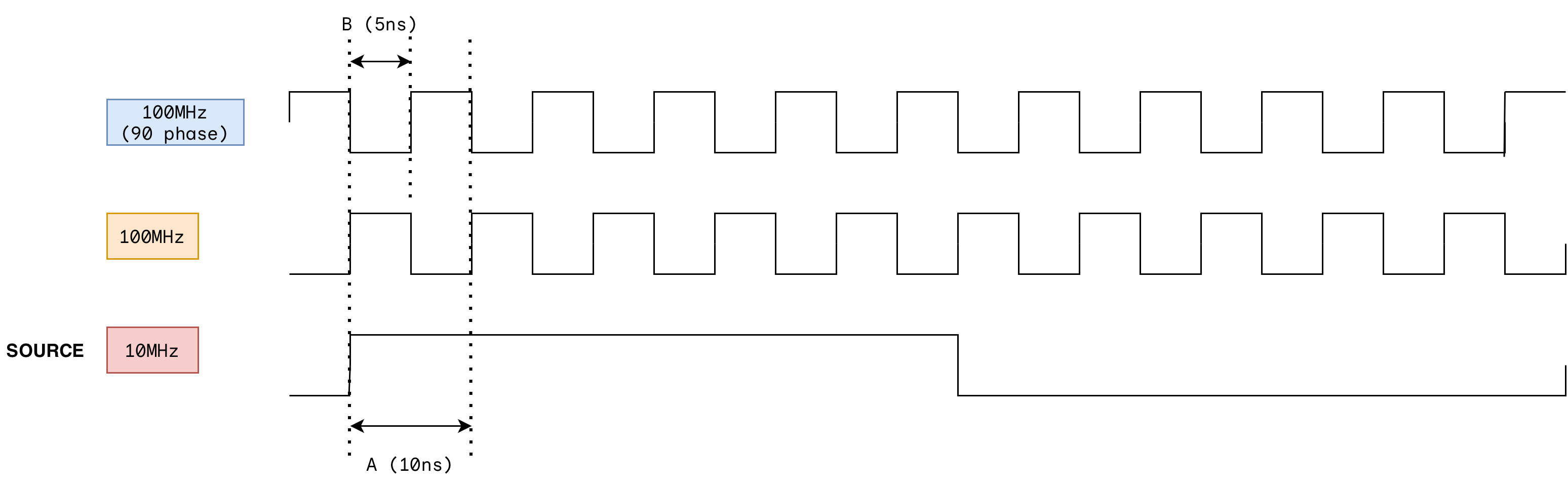
- Slow clock, 10 MHz, period 100 ns. Launch edges at t = 0, 100, 200, 300, …
- Fast clock, 100 MHz, period 10 ns. Capture edges at t = 0, 10, 20, 30, …, 90, 100, 110, …
- Assume they are aligned at t = 0 for simplicity.
-setup 10
-setup 10 moves the setup capture edge 10 fast clock cycles later, from t = 10 ns to t = 100 ns. Data launched at t = 0 now has 100 ns to arrive. Our maximum datapath delay is 100ns. This makes setup passes easily.
-hold 0
For this, Vivado automatically moves the hold check to follow the NEW setup edge at t = 100ns. The default hold capture edge is “one destination clock cycle before the setup capture edge” because that is the previous edge the tool is trying to protect. Since the destination clock cycle is 100MHz (10ns period), the new hold capture edge is computed at 100 ns - 10 ns = 90ns. At this point, Vivado does a hold check.
Hold Check
When new data is launched, it must not arrive at the destination FF so fast that it overwrites whatever the previous capture edge was supposed to sample. We begin by figuring out the hold capture edge, and adding tHold + clock skew into it to compute a hold check.
In the single cycle case (launch at t = 0, setup capture at t = 10), the hold capture edge is at t = 10 - 10 = 0. At t = 0, the destination FF is sampling the old value from the previous launch, say A, while the source FF is sampling a new value, say B. See figure below.
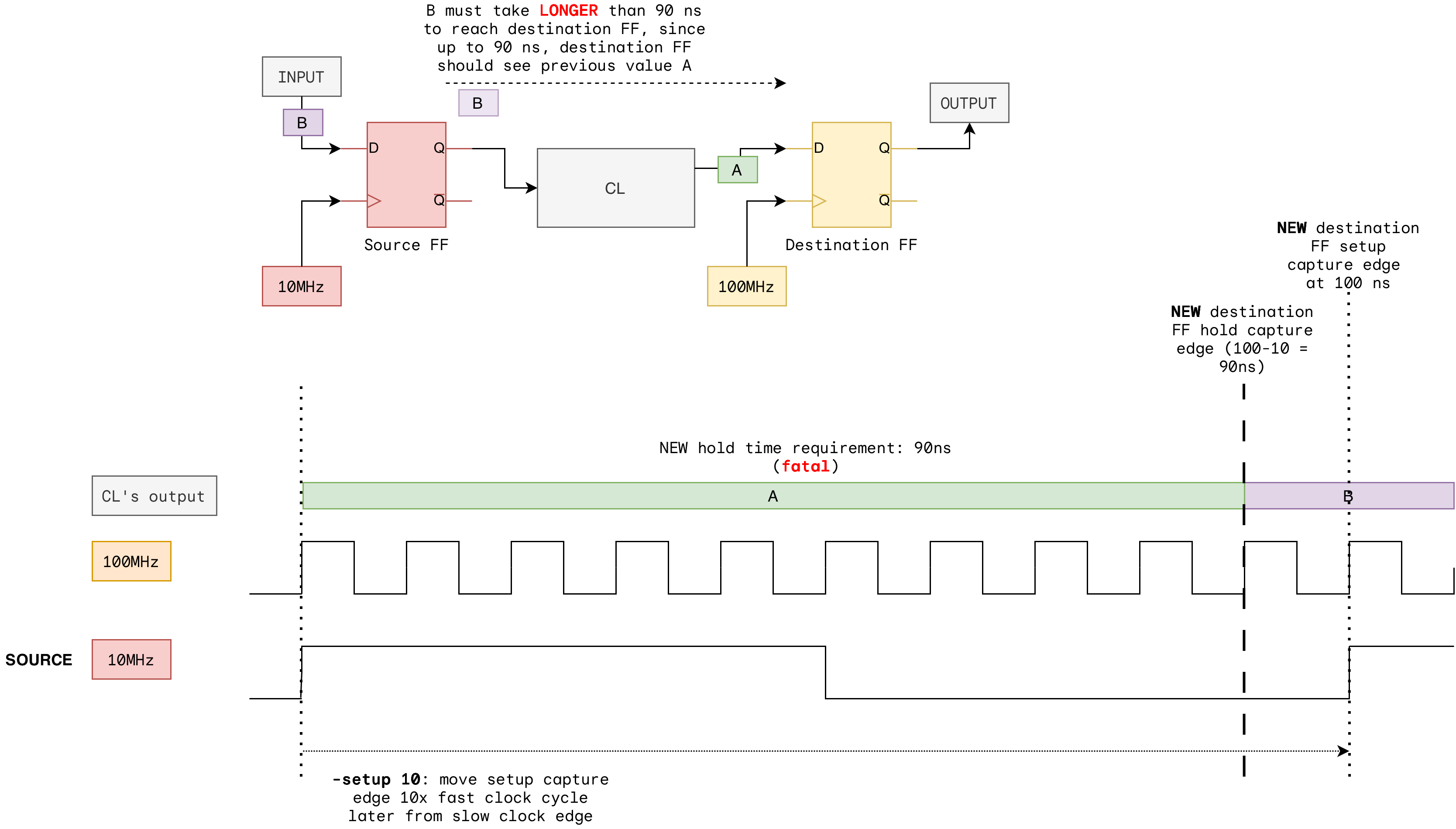
The hold check rule says the B must NOT reach the FF before t = 0 + thold FF Destination + clock skew, because this destination FF is trying to sample A. In other words, B should take MORE THAN min datapath delay > hold capture edge + thold FF + clock skew to reach destination FF. If hold capture edge is very small or 0 then this is trivially satisfied through the CL’s tcd.
From our lecture materials, we know that any real path from one FF to another through even a trivial amount of logic can automatically satisfies hold in the single cycle same clock case.
In the multicycle case with -setup 10:
- New setup capture edge: t = 100 ns.
- New hold capture edge: t = 100 - 10 (period of destination FF clock) = 90 ns.
So the tool places the hold check at t = 90 and says: “at t = 90 ns I am going to clock this FF and I expect it to capture some previous value A, NOT our new value B launched at t = 0. Therefore B must not reach the FF before t = 90.”. In other words, min datapath delay must be at least 90 ns. This is impossible to fulfil.
Real min datapath delay through a few complex LUTs and some routing is maybe 2 to 40+ ns. The tool reports a hold violation of roughly 60-80+ ns which is not fixable.
Therefore violation is catastrophic and nothing the router can do will fix it, because no one puts 90 ns of min delay on a real combinational path. The -hold 0 setting means “shift the hold check by zero cycles from its default position,” but the default position is already the broken one at t = 90 ns. So -hold 0 is a no-op and the violation stays exactly where it was.
Key point
The destination FF still has a rising clock edge every 10 ns. Edges at t = 10, 20, 30, …, 90, 100, … are all real clock events on the FF. The STA tool, by default, treats every one of those edges as a real capture that must sample the correct value. It has no notion of “this edge is a don’t care because my downstream logic ignores it.” You know those intermediate edges do not matter but the tool does not.
-hold 9 does not work either
For same frequency multicycle (say 100 MHz to 100 MHz with -setup 10), -hold 9 moves the hold check back 9 cycles and lands it at t = 0 ns again, which is where it was before the multicycle was applied. This is a clean cancellation and same frequency multicycle works.
For cross frequency, Vivado’s edge counting is asymmetric: -setup N counts N in destination (fast) clock cycles by default, but -hold N counts N in source (slow) clock cycles by default.
-setup 10moves the setup check by 10 fast cycles = 100 ns. Good.-hold 9tries to move the hold check back by 9 slow cycles = 9 * 100 = 900 ns. That shoots past t = 0 and lands at t = -810 ns. The tool either rejects it, re-pairs against a different launch edge, or turns the problem back into a setup violation elsewhere.
You can work around this with -hold N -end to force destination cycle counting, or compute a different N, but now you are patchwork against an STA engine whose edge pairing rules for asynchronous or unrelated clocks are not fully documented. It is easy to get wrong and hard to verify. This is not recommended.
Attempt 2: set_max_delay -datapath_only
We should instead use:
set_max_delay -datapath_only <VALUE> -from [get_clocks slow_clk] -to [get_clocks fast_clk]
The <VALUE> should be a little less than the slow clock period, to leave margin. In this example, we can use 90.0 (90 ns).
This is a different approach from the above. set_max_delay -datapath_only bounds raw propagation delay (Tcq + Tlogic + Trouting <= N ns) with no capture edge and no Tsetup in the check. set_multicycle_path -setup N keeps the normal edge-based setup check (Tcq + logic + routing + Tsetup + uncertainty included) but moves the capture edge out to N destination cycles later instead of the default 1. We have illustrations in the next section.
-datapath_only does two things at once:
- It caps the datapath delay at the value you specify. This is the real physical constraint: the signal just needs to propagate through the logic before the next slow clock edge launches a new value.
- It tells Vivado to ignore clock skew and clock edge relationships on this path, which effectively disables the hold check for it. The tool treats the transfer as quasi static and trusts that the source register will not change before the destination has sampled it.
That second point is the key difference from set_multicycle_path. Multicycle keeps the hold check alive and tries to re-anchor it, which is where things go wrong for cross frequency paths. -datapath_only removes the hold check from the picture and only enforces the max delay you asked for.
Tell the tool that the path is a multicycle path, meaning the destination register is allowed to wait N fast clock cycles before capturing, instead of just one.
set_multicycle_path -from [get_clocks slow_clk_name] -to [get_clocks fast_clk_name] -setup N
set_multicycle_path -from [get_clocks slow_clk_name] -to [get_clocks fast_clk_name] -hold  0
Where N is the ratio of the fast clock period to the slow clock period (or however many fast cycles the signal is guaranteed to be stable for).
The setup constraint moves the capture edge N cycles later, giving the datapath N times as long to settle. The hold constraint is set to 0 when the source and destination clocks are asynchronous or have different frequencies.
Example
In our setup we have BRAM inference on both memory modules (instruction and data):
In simple_ram.v (instruction):
(* ram_style = "block" *) reg [WIDTH-1:0] ram [ENTRIES-1:0];
In simple_dual_port_ram.v (data):
(* ram_style = "block" *) reg [WIDTH-1:0] mem [ENTRIES-1:0];
The purpose of this is to avoid them being built as LUT ROM with massive logic levels.
We set the Memory clock to 50MHz (90 degree phase offset), CPU clock to 6.25 MHz, and GPU clock to 25MHz using MMCM. Both of its PC and regfile capture on the same rising edge of 6.25 MHz. The CPU is much more complex than the GPU and must run on slower clock. The full 160ns period gives plenty of room for any required combinational length in the CPU. Both of them are sharing the data RAM, time-multiplexed. The BRAM receives read data address from CPU on posedge 25MHz clock, and address from GPU on negative 25MHz clock.
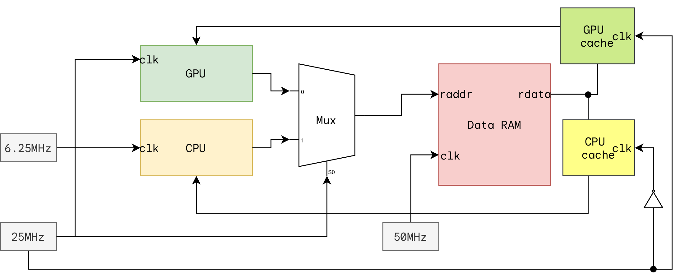
Therefore, shared memory needs a cache to both GPU and CPU:
reg [31:0] cpu_inst_cache;
reg [31:0] cpu_data_cache;

always @(negedge mhz_25) begin
    cpu_inst_cache <= M_memory_unit_id;
    cpu_data_cache <= M_memory_unit_mrd;
end

id  = cpu_inst_cache;
mrd = cpu_data_cache;
Initial Issue
Without the relaxed cross-clock paths, we are unable to pass timing, in particular, the path from 6.25MHz clock edge to the next 50MHz clock edge. Assuming that rising 6.25MHz happens at t, t+160, then rising edges of 50MHz happens at t+10, t+30, t+50, t+70, etc.
At t+10, the CPU is still computing EA for the memory. We need to wait several posedge 50MHz after t (at least 40 ns after). We can allow the RAM to capture a “wrong” value at t+10. This is not an issue as the CPU regs only capture RAM’s output at the following 6.25MHz, 160 ns later after t.
Solution
We set max delay between the various source clock and destination clock to be 150ns, just slightly under 160 ns (period of 6.25 MHz slowest clock):
# timing.xdc
# Constraint 1: CPU output to BRAM address
set_max_delay -datapath_only 110.0 -from [get_clocks mhz_6_25_clk_wiz_0_1] -to [get_clocks mhz_50_clk_wiz_0_1]
# Constraint 2: CPU cache to CPU Regs
set_max_delay -datapath_only 90.0 -from [get_clocks mhz_25_n_clk_wiz_0_1] -to [get_clocks mhz_6_25_clk_wiz_0_1]
# Constraint 3: CPU cache to BRAM address
set_max_delay -datapath_only 70.0 -from [get_clocks mhz_25_n_clk_wiz_0_1] -to [get_clocks mhz_50_clk_wiz_0_1]
The following timing diagram shows the reasoning behind the values 110 ns and 70 ns.
Paths behind each constraint:
- Constraint 1: This shows the maximum allowable delay for the CPU regs to produce a valid RAM read address. It is measured from the moment CPU received valid instruction data (id) to the last posedge 50MHz clock when 25MHz is HIGH (CPU slot) within 6.25MHz period.
- Constraint 2: CPU cache is clocked on negedge 50MHz in our setup. We measure the maximum datapath delay for this constraint from the moment the RAM is able to produce some data as per the current id, up until just slightly before the rising edge of 6.25MHz clk (CPU Regs capture time).
- Constraint 3: This path is unused in our design, because we would never need to load something out from the RAM and use it back as an input address to the RAM. However, Vivado would still consider this path, so we include it in our timing constraints.
Application Notes
set_max_delay -datapath_only is correct when the source signal is genuinely stable for longer than the datapath delay, and when you do not need a cycle accurate relationship between source and destination. Typical valid cases:
- A register clocked by a slower clock feeding logic in a faster domain where the value only changes once per slow cycle
- Control signals that are held for the duration of a transaction (enables, mode bits, addresses)
- Quasi static configuration coming from one clock domain into another
It is not safe when the signal can change on any fast clock edge, or when the receiver actually needs to know which destination cycle the data arrived in. For those cases the correct answer is a proper clock domain crossing: a synchroniser for single bit control, or a handshake or async FIFO for multi bit data.
Summary
The default STA behaviour for cross clock paths is to demand the datapath settle within the worst edge pairing between the two clocks, which for 10 MHz to 100 MHz is 10 ns rather than the real 100 ns the signal actually has.
set_multicycle_path -setup 10 fixes the setup side but causes Vivado to move the hold check to t = 90 ns, creating an 85 ns hold violation that neither -hold 0 nor -hold 9 can fix cleanly, because setup and hold are counted in different reference clocks for cross frequency paths. set_max_delay -datapath_only sidesteps the entire hold arithmetic problem by capping the datapath delay and telling the tool not to run a hold check on the path at all, which is the right model for a quasi static cross clock transfer.