 50.002 CS
50.002 Computation Structures
Information Systems Technology and Design
Singapore University of Technology and Design
Driving RGB LED Matrix (HUB 75) with an FPGA
Driver Code
You can download the driver code from here.
This driver is meant for 2/N scan rate only, where N is the number of rows (smaller dimension) of the matrix.
Overview
An RGB LED matrix is a grid of LEDs where each pixel consists of three sub-pixels (Red, Green, Blue). By adjusting the brightness of these sub-pixels, the matrix can display full-color images and animations. Example of such matrix is the Adafruit RGB LED Matrix.
Connection
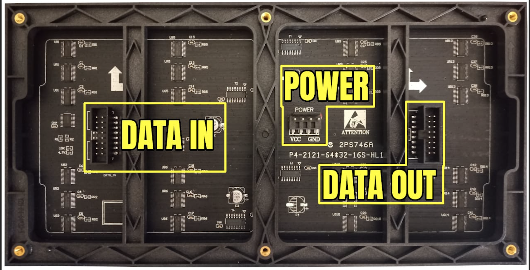
HUB75 is a parallel interface standard used in RGB LED matrices to reduce the number of wires needed for control (refer to image above, taken from this source). Instead of having a dedicated wire for each pixel, it uses row scanning and shift registers.
- Only a subset of rows are active at a time (multiplexing).
- Shift registers store pixel data for the active row.
- Address lines select which row to light up.
- This process is repeated rapidly to create a full image.
The table below summarizes the purpose of each pin. Image taken from this source.
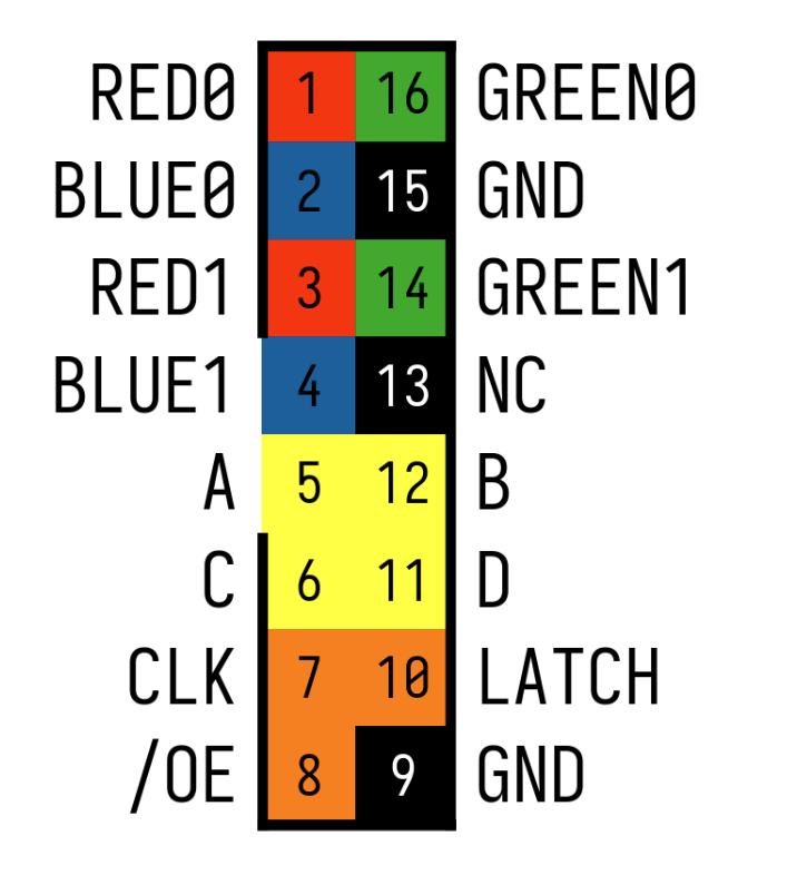
| Pin | Name | Function |
|---|---|---|
| 1 | R0 | Red channel for the top half |
| 2 | G0 | Green channel for the top half |
| 3 | B0 | Blue channel for the top half |
| 4 | R1 | Red channel for the bottom half |
| 5 | G1 | Green channel for the bottom half |
| 6 | B1 | Blue channel for the bottom half |
| 7 | A | Row selection bit 0 |
| 8 | B | Row selection bit 1 |
| 9 | C | Row selection bit 2 |
| 10 | D | Row selection bit 3 (used for larger matrices) |
| 11 | CLK | Shift register clock |
| 12 | LAT | Latch (stores shifted data) |
| 13 | OE | Output Enable (turns display on/off) |
| 14 | GND | Ground |
| 15 | E | Row selection bit 4 (for 64-row matrices) |
| 16 | GND | Ground |
If you use a ribbon connector, mirror the connection. Watch where the “red” line is to know your orientation:
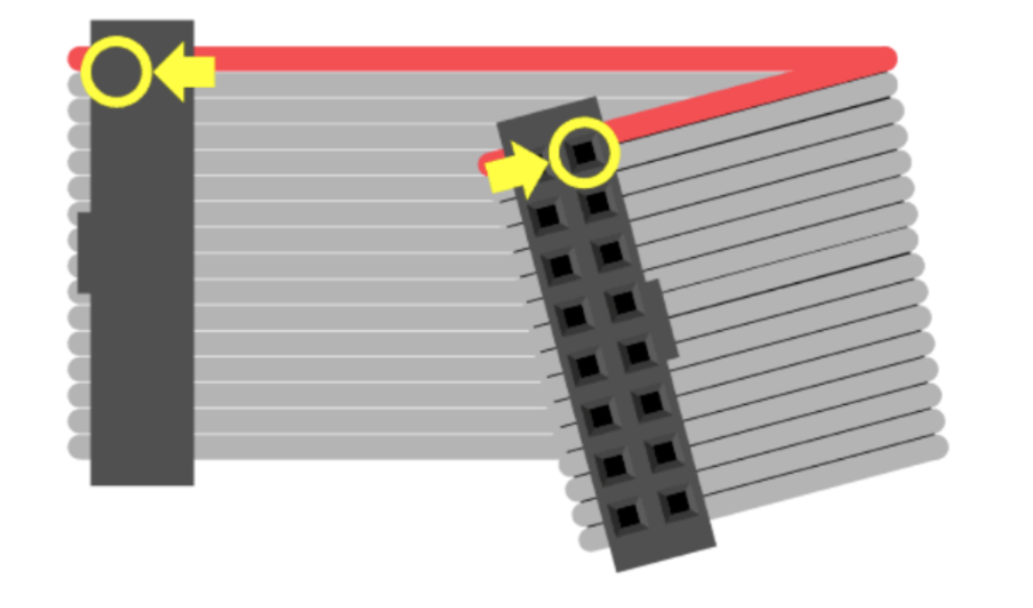
This is what we end up with:

Scan Rate
Scan rate determines how the matrix refreshes. 1/N Scan Rate means 1 out of every N rows is active at a time.
Common scan rates:
- 1/16 scan (64x32 panels)
- 1/8 scan (32x16 panels)
- 1/4 scan (some 32x16 panels, not supported in this driver)
- The lower the scan ratio, the brighter the display (since each row is on more often).
This driver is meant for 2/N scan rate only, where N is the number of rows (smaller dimension) of the matrix. Since only two rows are driven at any given time, the display is rapidly refreshed to create the illusion of a full image.
Refreshing the Display
The LED matrix needs to be constantly refreshed:
- Pixel data is loaded row by row into shift registers.
- The latch signal (LAT) stores the row’s data.
- The address lines select the next active row.
- The blank signal (OE) turns LEDs off briefly during row switching.
- The process repeats continuously at a high speed (hundreds or thousands of times per second).
Power Requirements
These matrices run on 5V power and consume high current. A 64x32 panel can easily draw 4–10A depending on brightness. Higher voltages can damage the LEDs and controller circuits.
Implementation
The driver implementation can be found in the file rgb_led_matrix_driver.luc.
Demo Code
The demo project utilising the driver can be found here. Consult its readme on how to operate it.