 50.002 CS
50.002 Computation Structures
Information Systems Technology and Design
Singapore University of Technology and Design
Driving WS2812B LEDs with an FPGA
Driver Code
You can download the driver code from here.
Overview
WS2812B LEDs are individually addressable RGB LEDs with an integrated driver chip. They use a single-wire protocol to receive data and control color. Since each LED in a strip or matrix can store its own color information, a long sequence of LEDs can be controlled with just one data pin.
Connection
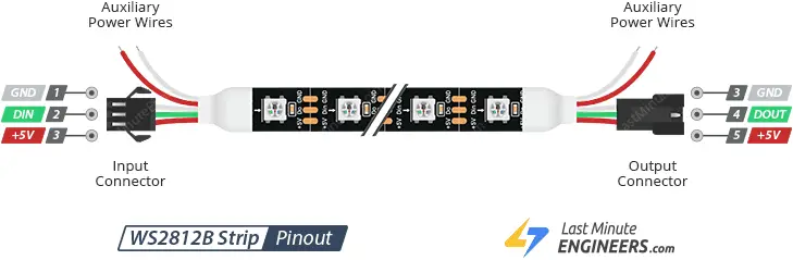
Connect Din directly to FPGA GPIO Pin, GND to FPGA GND, and +5V to FPGA +5V Ports. If you use external power, ensure that GND is shared between the FPGA and WS2812B.
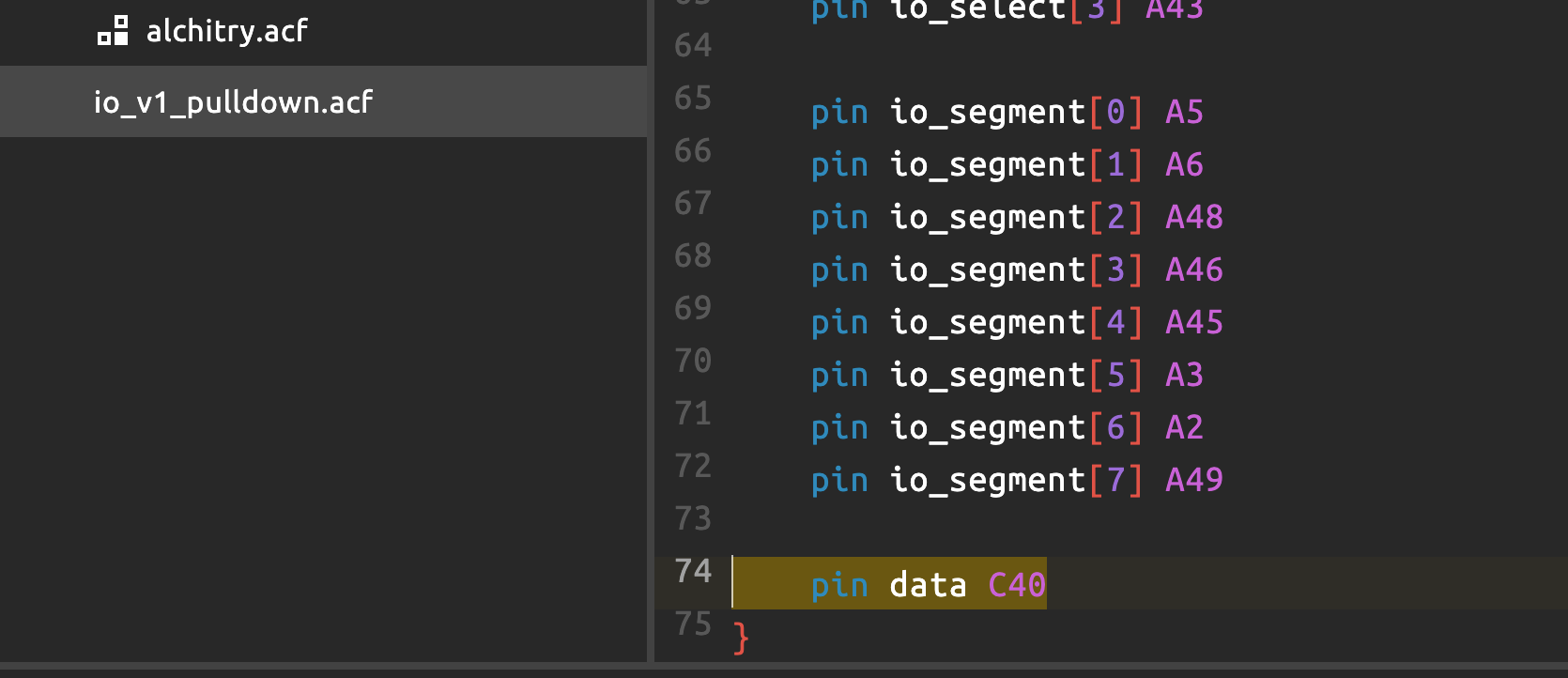
In the sample code above, you should connect Din to pin C40 as defined in the constraint file:
How WS2812B Works
- Each LED contains a red, green, and blue LED with 8-bit brightness control (0–255).
- Data is sent serially in 24-bit GRB format:
- 8 bits for Green
- 8 bits for Red
- 8 bits for Blue
- The LEDs store the data and pass the remaining data down the strip.
- A reset signal (low for >50 µs) tells the LEDs to update their colors.
Communication Protocol
WS2812B uses a pulse-width encoding scheme to differentiate between 1 and 0:
| Bit Value | High Time | Low Time | Total Period |
|---|---|---|---|
| 0 | 0.4 µs | 0.85 µs | 1.25 µs |
| 1 | 0.8 µs | 0.45 µs | 1.25 µs |
- The timing must be precise, requiring accurate pulse generation from the FPGA.
For a 100MHz clock, we have:
| Bit Value | High Time | Low Time | Total Period | High Cycles (100 MHz) | Low Cycles (100 MHz) | Total Cycles |
|---|---|---|---|---|---|---|
| 0 | 0.4 µs | 0.85 µs | 1.25 µs | 40 cycles | 85 cycles | 125 cycles |
| 1 | 0.8 µs | 0.45 µs | 1.25 µs | 80 cycles | 45 cycles | 125 cycles |
| RESET | Low for >50 µs | 5000 cycles (minimum) |
Explanation:
- Each WS2812B bit takes 1.25 µs = 125 cycles at 100 MHz.
- A logic ‘0’:
- High for 40 cycles (0.4 µs)
- Low for 85 cycles (0.85 µs)
- A logic ‘1’:
- High for 80 cycles (0.8 µs)
- Low for 45 cycles (0.45 µs)
- Reset signal:
- Hold data line low for at least 50 µs (5000 cycles at 100 MHz).
Adjust the values above accordingly for other clock frequencies.
Sending Data to WS2812B
- Send a 24-bit color value for each LED in the GRB format.
- Ensure correct timing of
1and0bits using precise pulse widths. - Send a reset signal (low for >50 µs) after all LEDs have received their data.
Implementation
The driver implementation can be found in the file ws2812b_driver.luc.
Demo Code
The demo project utilising the driver can be found here. Consult its readme on how to operate it.