 50.002 CS
- Starter Code
- Related Class Materials
- Part 2 Introduction
- Task 1: Multiplier Unit
- Task 2: Assembling the ALU
- Summary
50.002 Computation Structures
Information Systems Technology and Design
Singapore University of Technology and Design
Modified by: Natalie Agus (2024)
Lab 3: Arithmetic Logic Unit
Starter Code
Continue to work on your ALU project from the previous lab.
Since there’s only 1 FPGA per group, you need to work through this lab as a 1D group during class. However each person must still submit the lab questionnaire individually.
You are not required to submit your code for this lab. You will need it anyway for your 1D Project Checkoff 1: ALU and you should submit it then. Simply head to eDimension and do the lab questionnaire by the stipulated due date.
Related Class Materials
The lecture notes on Logic Synthesis and Designing an Instruction Set are closely related to this lab.
Part 2: Design a multiplier and combine it with each combinational element in Part 1 to form an ALU
Related sections in the notes: Designing an Instruction Set
- Basics of programmable control systems (using control signals like ALUFN to perform different operations (
ADD,SHIFT,MUL, etc) between two 32-bit inputs A and B in the same ALU circuit – no hardware modification needed).
Remember that you are NOT allowed to use any of Lucid’s math and comparison operators when implementing this lab’s ALU 13 functionalities. This is the requirement of your 1D project because we would like you to learn the basics and not solely rely on Vivado’s capability on creating components of the ALU. Please follow the implementation of the units from the given schematics. Failure to comply will result in -2% of your overall grades. However, you can use them for array indexing (bit selection) or checking conditions in loops.
Part 2 Introduction
In thit Part 2 of our ALU lab, we will implement a 32-bit multiplier unit and then assemble each of the components we have crated in Part 1 plus the multiplier to form a 32-bit ALU.
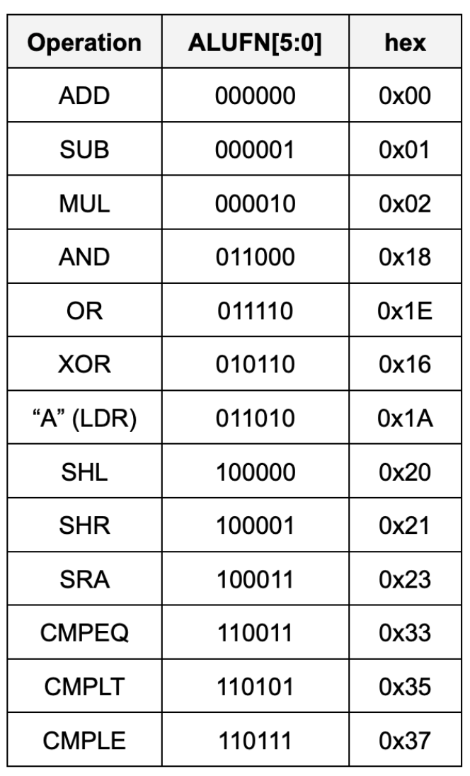
The ALU can perform the following 13 arithmetic operations:
Think!
Remember that an ALU is a combinational logic device. It has a certain
tpdandtcd. We use 6-bitALUFNcontrol signal to perform any of the 13 operations. Could you guess which operation determines thetpdof the ALU? What about itstcd?
Task 1: Multiplier Unit
The multiplier unit performs a multiplication between 32-bit inputs A and B each, and produce a 32-bit output.
Multiplying two 32-bit numbers produces a 64-bit product in practice, but the result we’re looking for is just the low-order 32-bits of the 64-bit product.
4-bit Multiplication Logic
It’s hard to imagine a 32-bit multiplier straight up, so let’s scale down to a 4-bit version.
Suppose we want to multiply two 4-bit binary numbers: A = 1011 (which is 11 in decimal) and B = 1101 (which is 13 in decimal).
The multiplication process involves the following steps:
- Write Down the Multiplicands: Write A and B such that each bit of B is aligned under each bit of A.
- Multiply Each Bit of B by A: Multiply each bit of B with the entire number A, shifting the result to the left for each subsequent bit. In binary multiplication, this means we either take A (if the bit in B is 1) or take 0 (if the bit in B is 0).
- Add the Partial Products: Add all the partial products together to get the final result.
    1011   (A = 11 in decimal)
  x 1101   (B = 13 in decimal)
  ------
    1011   (This is A * 1; the rightmost bit in B is 1)
   0000    (This is A * 0; shift left by 1 because we're on the second bit from the right in B)
  1011     (This is A * 1; shift left by 2)
 1011       (This is A * 1; shift left by 3)
------
10001111   (Sum of the above partial products)
Here is a detailed bit-level description of how a 4-bit by 4-bit unsigned multiplication works. This diagram assumes we only want the low-order 4 bits of the 8-bit product.
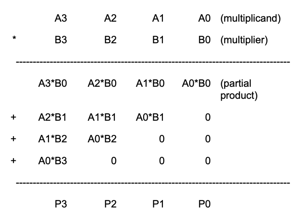
This diagram can be extended in a straightforward way to 32-bit by 32-bit multiplication. Remember that since our machine is only 32-bit, that means we only can store the low-order 32-bits of the result, we don’t need to include the circuitry that generates the rest of the 64-bit product.
4-bit Multiplier Schematic
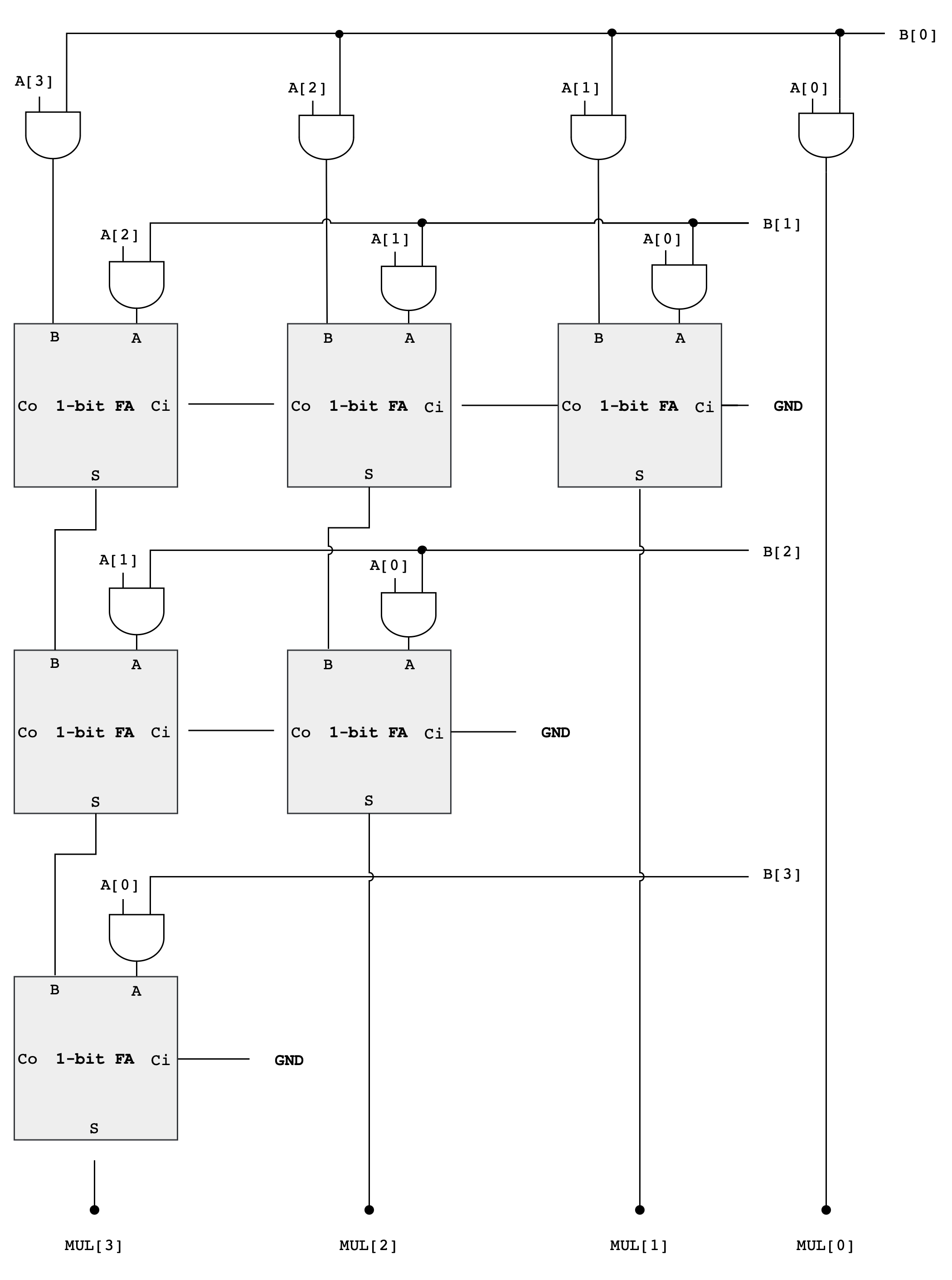
As you can see from the diagram above, forming the partial products is easy. Multiplication of two bits can be implemented using an AND gate. The hard and tedious part is adding up all the partial products (there will be 32 partial products in your circuit).
- One can use FA units hooked up in a ripple-carry configuration to add each partial product to the accumulated sum of the previous partial products (see the diagram below)
- The circuit closely follows the diagram above but omits an FA module if two of its inputs are
0
Multiplier Analysis
The circuit above works with both unsigned operands and signed two’s complement operands.
Think!
This may seem strange, don’t we have to worry about the most significant bit (MSB) of the operands? With unsigned operands the MSB has a weight of \(2^{MSB}\) (assuming the bits are numbered 0 to MSB) but with signed operands the MSB has a weight of \(-2^{MSB}\).
Doesn’t our circuitry need to take that into account?
Turns out it does, but when we are only saving the lower half of the product, the differences don’t appear. The multiplicand (A in the figure above) can be either unsigned or two’s complement (signed), and the FA circuits will perform correctly in either case.
When the multiplier (B in the figure above) is signed, we should subtract the final partial product instead of adding it.
- But subtraction is the same as adding the negative, and the negative of a two’s complement number can be computed by taking its complement and adding 1.
- When we work this through we see that the low-order bit of the partial product is the same whether positive or negated.
The low-order bit is ALL that we need when saving only the lower half of the product.
If we were building a multiplier that computed the full product, we’d see many differences between a multiplier that handles unsigned operands and one that handles two’s complement (signed) operands, but these differences only affect how the high half of the product is computed.
Example: 4-bit Signed Multiplication
Let’s use a 4-bit example to illustrate why the lower half of the product is the same whether we are dealing with signed or unsigned numbers, especially in the context of two’s complement arithmetic.
Suppose we have A = 0110 (6 in decimal) multiplied by B = 1101 (-3 in decimal, two’s complement).
As Unsigned Numbers, they are:
A = 0110(6 in decimal)B = 1101(13 in decimal, treated as unsigned)
The multiplication (ignoring overflow) of these two numbers is:
   0110   (A = 6)
 x 1101   (B = 13, as unsigned)
 ------
   0110   (A * 1)
  0000    (A * 0, shift left by 1)
 0110     (A * 1, shift left by 2)
0110      (A * 1, shift left by 3)
------
1001110   (78 in decimal, unsigned)
However, the multiplication as signed numbers works differently because the last partial product should be negated:
    0110   (A = 6)
  x 1101   (B = -3, as signed)
  ------
    0110   (A * 1)
   0000    (A * 0, shift left by 1)
  0110     (A * 1, shift left by 2)
 1010000   (A * 1, shift left by 3, we get 0110000 but it should be negated, resulting in 1010000)
------
 1101110 (-18 in decimal, signed)
If you’re confused, realise that the negation of 0110000 is 1010000 (flip the bits, then add 1).
In both cases, the lower half of the product (1110) is the same. This is because the difference caused by the negative MSB in the two’s complement representation affects only the higher-order bits, which are outside the lower half of the product.
When multiplying two numbers where the sign of one is significant (like in two’s complement), the alterations to the upper bits due to the sign are not reflected in the lower bits. This is why, in certain computational scenarios where only the lower half of the product is of interest, the circuitry can be simplified as it doesn’t need to differentiate between signed and unsigned numbers.
Design Note
Combinational multipliers implemented as described above are pretty slow! There are many design tricks we can use to speed things up – see the appendix on “Computer Arithmetic” in any of the editions of Computer Architecture: A Quantitative Approach by John Hennessy and David Patterson (Morgan Kauffmann publishers).
Test
As usual, please test your multiplier circuit properly before proceeding. Think of useful test cases, such as multiplication by 0, multiplication by -1, and multiplication by two positive numbers.
Connect the output of your multiplier to the output of your alu for now:
// alu.luc body

  alu.out = multiplier.mul;
Task 2: Assembling the ALU
Combine the outputs of the finished adder, multiplier, compare, boolean and shift units to produce a single ALU output: ALU[31:0]. The simplest approach is to use a 4-way 32-bit multiplexer as shown in the schematic below:
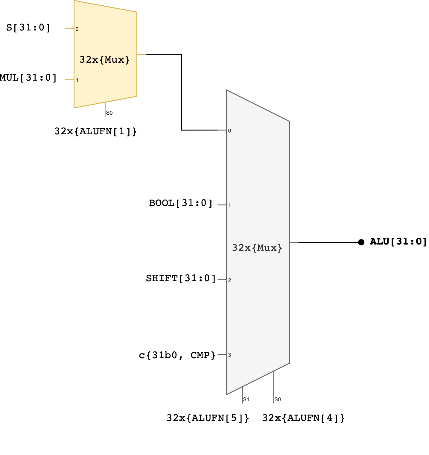
You can utilise
MUX_4.lucyou’ve created before if you’ve followed Part 1 handout closely.
Two control signals (ALUFN[5:4]) that we have never used before in the individual module have now been utilised to select which unit will supply the value for the ALU output. The encodings for ALUFN[5:0] should follow this table that you’ve seen in the beginning of this handout:
Note that the Z, V, and N signals from the adder/subtractor unit are included in the terminal list for the alu subcircuit (they’re counted as ALU’s output). Please connect these terminals properly in your alu.luc file.
Test
Be sure to test your ALU comprehensively. Here’s some suggestions (you’re not limited to these, think of more!):
- ADD (0x00)
- Zero Addition:
A + 0and0 + Ato ensure correct handling of zero. - Positive Numbers: Add two positive numbers.
- Boundary Values: Add the maximum positive number to itself and ensure correct handling of overflow.
- Check for overflow by adding two very big positive numbers
- Zero Addition:
- SUB (0x01)
- Zero Subtraction:
A - 0and0 - Ato test for correct subtraction with zero. - Underflow: Subtract a larger number from a smaller one to test for underflow.
- Boundary Values: Subtract the maximum positive number from zero and check for correct negative result in two’s complement.
- Zero Subtraction:
- MUL (0x02)
- Zero Multiplication: Multiply by 0 to ensure the result is 0.
- Multiplication by One:
A * 1should yieldA. - Positive Numbers: Multiply two positive numbers and check for correct results.
- Overflow (not compulsory, only if it’s relevant to your project): Multiply two numbers that will cause overflow and ensure it is handled correctly.
- AND (0x18)
- All Zeros and Ones:
A AND 0should be 0,A AND 0xFFFF(assuming 16-bit operands) should beA. - Identity Check:
A AND Ashould giveA. - Complement Check:
A AND NOT Ashould give 0.
- All Zeros and Ones:
- OR (0x1E)
- All Zeros and Ones:
A OR 0should beA,A OR 0xFFFFshould be 0xFFFF. - Identity Check:
A OR Ashould giveA.
- All Zeros and Ones:
- XOR (0x16)
- Identity Check:
A XOR 0should giveA,A XOR Ashould give 0. - Complement Check:
A XOR NOT Ashould give 0xFFFF.
- Identity Check:
- “A” (LDR) (0x1A)
- Load Function: Ensure that inputting
AgivesA, and does not modify it.
- Load Function: Ensure that inputting
- SHL (0x20)
- Zero Shift: Shifting
Aby 0 should yieldA. - Maximum Shift: Shifting a number by the width of the data bus minus one.
- Boundary Cases: Shift a number with a 1 in the MSB and ensure it is handled correctly.
- Zero Shift: Shifting
- SHR (0x21)
- Zero Shift: Shifting
Aby 0 should yieldA. - Maximum Shift: Shifting a number by the width of the data bus minus one.
- Logical Shift: Ensure that the vacated bits are filled with 0.
- Zero Shift: Shifting
- SRA (0x23)
- Arithmetic Right Shift: Ensure the sign bit is replicated to preserve the sign of the number.
- CMPEQ (0x33)
- Equality: Test with equal values to ensure the result is true.
- Inequality: Test with different values to ensure the result is false.
- CMPLT (0x35)
- Less Than: Test where
Ais less thanB. - Greater Than or Equal: Test where
Ais greater than or equal toBto ensure the result is false.
- Less Than: Test where
- CMPLE (0x37)
- Less Than or Equal: Test where
Ais less than or equal toB. - Greater Than: Test where
Ais greater thanBto ensure the result is false.
- Less Than or Equal: Test where
Testing tips
You should use the fsm component to test your ALU properly instead of using the buttons to hardcode values of A and B. If you follow the notes closely, you notice that bit 16 to 23 is always hardcoded as 0:
a.d = c{io_dip[2], 8b0, io_dip[1], io_dip[0]}; // set io_dip[2] to dictate MSB 8 bits
What if we want to key in all 32-bits value of A? We need to leverage the fsm. You can declare an fsm in au_top as follows. There are 6 different states, each indicating whether we are setting the lower or higher 16 bits of A, and B, as well as the ALUFN, and then putting the fsm into RUN state.
fsm alu_runner(.clk(clk), .rst(rst)) = {SET_A_16, SET_A_32, SET_B_16, SET_B_32, SET_ALUFN, RUN};
Now let’s use io_button[4] to advance the fsm to next state, and io_button[3] to allow it to move from RUN to SET_A_16 again. We need to modify the button_conditioner and utilise an edge_detector because we want to use our buttons as triggers to transition the fsm to a different state exactly once per button press:
   // in .clk block
   button_conditioner button_conditioner[5];
   edge_detector edge_detector[2](#RISE(1), #FALL(0));

   // in always block
   button_conditioner.in = io_button[4:0];
   edge_detector.in = button_conditioner.out[4:3];
Then we need to dictate what happened during each state in the always block. Below is one example:
case (alu_runner.q){
        alu_runner.SET_A_16:
          if (edge_detector.out[1]){
            a.d = c{a.q[31:16], io_dip[1], io_dip[0]};
            alu_runner.d = alu_runner.SET_A_32;
          }

        alu_runner.SET_A_32:
          if (edge_detector.out[1]){
            a.d = c{io_dip[1], io_dip[0], a.q[15:0]};
            alu_runner.d = alu_runner.SET_B_16;
          }

        alu_runner.SET_B_16:
          if (edge_detector.out[1]){
            b.d = c{b.q[31:16], io_dip[1], io_dip[0]};
            alu_runner.d = alu_runner.SET_B_32;
          }

        alu_runner.SET_B_32:
          if (edge_detector.out[1]){
            b.d = c{io_dip[1], io_dip[0], b.q[15:0]};
            alu_runner.d = alu_runner.SET_ALUFN;
          }

        alu_runner.SET_ALUFN:
          if(edge_detector.out[1]){
            alufn.d = io_dip[0][5:0];
            alu_runner.d = alu_runner.RUN;
          }

        alu_runner.RUN:
          if(edge_detector.out[0]){
            // set A again
            alu_runner.d = alu_runner.SET_A_16;
          }
      }
You will start the system with the fsm being in the SET_A_16 state, and will only advance to the next state when io_button[4] (right button) is pressed. At SET_A_16 state, we are capturing the states of io_dip[1] and io_dip[0] to the lower 16 bits of dff a[32]. Then you can press io_button[4] again to set A’s higher 16 bits and so on. Note that you might need to track which state you are at mentally as there’s no indication whatsoever. You can improve this by outputting a certain LED at the side of the FPGA when being at each state to indicate which state you’re currently at. We leave it up to you to decide.
Summary
Congratulations 🎉🎉! You have successfully built a 32-bit ALU in this lab and familiarse yourself with programming FPGA with Lucid. You will be required to utilise it in Lab 4 (Beta CPU), so please keep a copy of your answer.
For your 1D project, you will need to downsize the ALU to support 16-bit instead of 32-bit. It shouldn’t be too much work to modify. You might also want to consider creating automatic tester using the fsm module for your 1D Project Checkoff 1: ALU. Read the FPGA tutorials linked in our course handout for further information, and don’t forget to polish your knowledge on Sequential Logic before proceeding.
Please also read Checkoff 1: ALU schedule, requirements and rubrics given in the course handout carefully. Do not miss your checkoff slot.
For your Checkoff 1: ALU, you’re also required to create additional functionalities. You are allowed to use Lucid math and comparison operator for this NEW functionality. For example, if your new operation involves DIVISION between A and B, you’re allowed to implement it as follows:
// divide a by b
module divider (
    input a[32], // dividend
    input b[32], // divisor
    output d[32] // a/b
  ) {

  always {
    d = a/b;
  }
}
Only the original 13 functionalities must be implemented using logic gates as per the circuitry given in this lab handout.
When you’re done with the implementation of your ALU, head to eDimension to complete this week’s lab quiz.