- The “Nuts and Bolts” View
- The “Service” View
- Network Challenges
- Summary
- Appendix
50.005 Computer System Engineering
Information Systems Technology and Design
Singapore University of Technology and Design
Natalie Agus (Summer 2025)
Network Basics
Detailed Learning Objectives
- Identify Basic Concepts of Computer Networking
- List the basic definition and purpose of computer networks.
- Differentiate between the “nuts and bolts” and “service” views of networking.
- Explain the “Nuts and Bolts” of Computer Networking
- Identify the components that make up the internet including hosts, communication links, and packet switches.
- Describe the function and types of end systems, communication links, and packet switches.
- Assess the various types of Internet Service Providers (ISPs) and their roles in providing network access.
- Explain the “Service” View of the Internet
- Explain the internet as an infrastructure that provides services to applications.
- Give Examples on the role of APIs in enabling applications to access network services.
- Justify Network Challenges and Solutions
- Assess various network challenges such as operability, sharing, component interaction, and scalability in networking.
- Describe the methods used to overcome these challenges including internet protocols and APIs.
- Evaluate Network Layering and its Importance
- Describe the general concept of network layering and its role in reducing complexity and managing network interactions.
- Classify each layer in the network hierarchy from physical to application layer, and the respective roles and protocols associated with each layer
- Explain Data Transmission Methods
- Justify packet switching and circuit switching, understanding their advantages and applications.
- Calculate the time required for data transfer under different network configurations.
- Describe the Concept of Multiplexing
- Compare frequency division and time division multiplexing and their usage in network communications.
- Discuss Nuances about Protocols and Standards
- Identify and explain the significance of different network protocols across various layers.
- Examine how protocols like TCP, UDP, IP, Ethernet, and others function within the network stack.
- Analyze Practical Networking Examples
- Apply theoretical knowledge to practical examples, including calculations for data transfer and understanding traffic patterns.
- Explain the concept of priority inversion and emergent behavior
- Appraise more complex aspects of networking such as data encapsulation and the interaction between different network layers.
These learning objectives are intended to guide your understanding of the comprehensive notes on computer networking.
Computer Networking is the practice of connecting computers together to enable communication and data exchange between them. There’s two ways to define what the network is, but there’s no authoritative formal answer.
There are two views to computer networking: the nuts and bolts view and the service view. Each view help to conceptualize different aspects of how networks are built and function.
The “Nuts and Bolts” View
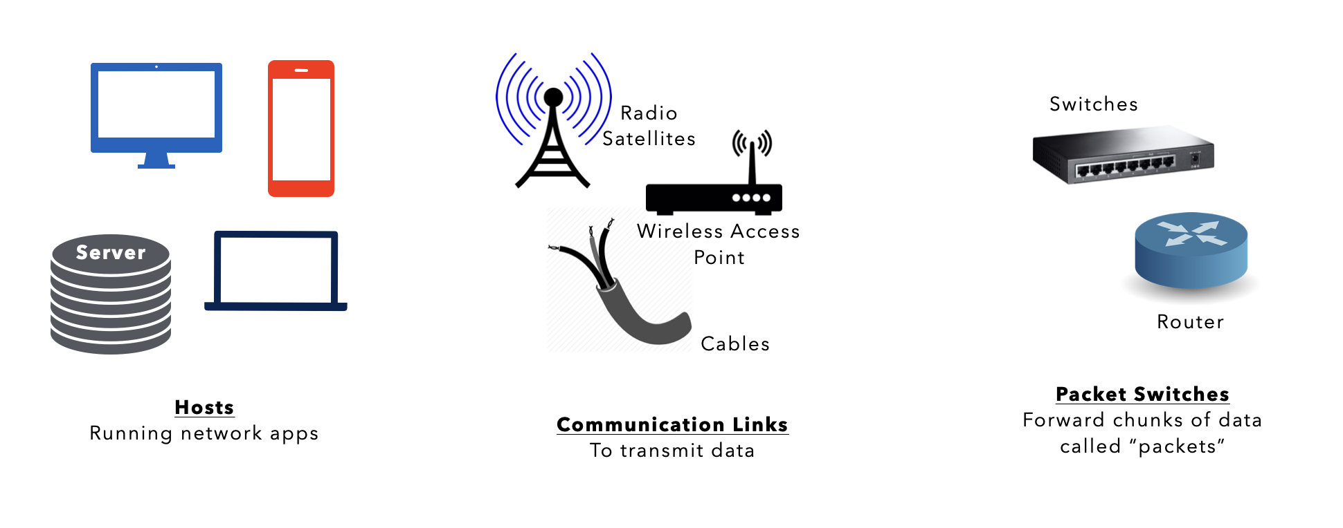
The Internet’s Nuts and Bolts
The internet is essentially made of hosts/end systems, communication links, and packet switches.
End systems are connected together by a network of these communication links and packet switches, essentially making it a network of networks. As of 2024, estimates indiicate there are over 200 billion devices connected globally, encompassing a wide range of tools, toys, devices, and appliances.
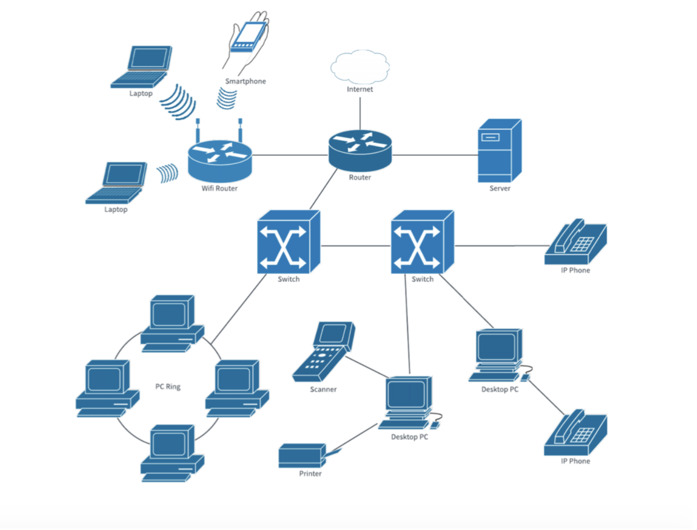
Below we list a few network jargons that are useful to enhance your understanding.
Host/End Systems
Host or End Systems
The end system devices are running network applications (programs).
These include your web browser, communication/chat programs such as Telegram, Skype, or Whatsapp, video game programs such as Steam, Battle.net, etc, or various server and database applications, basically any end devices that are running programs which require connection through the internet.
Communication Links
There are many types of communication links (different materials):
- Coaxial cable,
- Copper wire,
- Optical fiber,
- Radio spectrum.
Different links can transmit data at different rates, and transmission rate (bandwidth) of a link is measured in bits/second.
Packets
When one end system has data to send to another end system, the sending end system:
- Segments the data (into smaller chunks) and
- Adds header bytes to each segment (to know the order of the chunks)
The resulting packages of information, known as packets in the jargon of computer networks, are then sent through the network to the destination end system, where they are reassembled into the original data.
Packet Switches
A packet switch takes a packet arriving on one of its incoming communication links and forwards that packet on one of its outgoing communication links.
Types of packet switches include:
- Routers
- Link-layer switches
They both receive and forward packets, but we will discuss the differences between the two later on. The sequence of communication links and packet switches traversed by a packet from the sending end system to the receiving end system is known as a route or path through the network.
Internet Service Providers (ISPs)
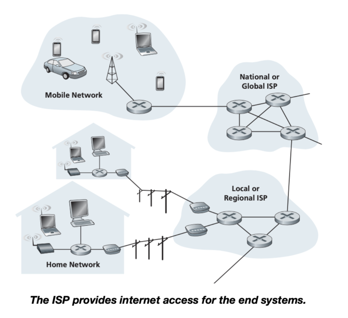
Examples of ISPs:
- Regional ISPs such as local cable or telephone companies (they’re bound by geographical boundaries)
- Global ISPs (not bound by geographical boundaries), also known as Tier 1 ISP (see this section): AT&T, Sprint, Verizon, etc
- Corporate ISPs;
- University ISPs;
- Other ISPs that provide WiFi access in airports, hotels, coffee shops, and other public places.
ISP
Each ISP is in itself a network of packet switches and communication links. ISPs provide a variety of types of network access to the end systems, including residential broadband access such as cable modem or DSL or wireless access.
ISPs also provide Internet access to content providers: a website or organization that handles the distribution of online content such as blogs, videos, music or files (Azure, Google, Cloudflare, Akamai, etc).
Since the Internet is all about connecting end systems to each other, the ISPs that provide access to end systems must also be interconnected.
The “Service” View
The Internet as a Service
The alternative definition of the internet is an infrastructure that provides services to applications.
This infrastructure does not only mean physical infrastructure for an internet, but also the programming interfaces (API) for these applications to use:
- APIs: libraries that allow apps to conveniently “connect” to the internet and send/receive packets securely through these APIs
- E.g: Socket API, REST API (for HTTPs)
These applications include, but are not limited to, the following, which we frequently use on a daily basis:
- E-mail,
- Web browsing,
- Social networking,
- Instant messaging,
- Voice-over-IP (VoIP),
- Video streaming,
- Distributed games,
- Peer-to-peer (P2P)
- File sharing (torrent, etc),
- Television over the internet,
- Remote login
These applications are said to be distributed applications, since they involve multiple end systems that exchange data with each other.
More importantly, internet applications run on end systems (we call this edges of the network), and not on packet switches in the network core.
Network edge includes hosts/end systems. Network core includes switches, routers.
Packet switches only facilitate the exchange of data among end systems, They are not concerned with the application that is the source or sink of data. The analogy of packet switches is much like delivery companies: DHL, Singpost.
Network Challenges
It is certainly a non-trivial challenge to connect a huge number of end hosts together using communication links and packet switches.
Some of the challenges include:
- Operability: How do the independent devices communicate and synchronize, what medium or protocols do they use?
- Sharing: How do we control traffic of packets? How do we share resources between N hosts that wish to communicate with one another?
- Complex interacting components: How do we manage the interaction between so many different types of devices, e.g: phones, micro controllers, computers, database servers, cars, etc?
- Scalability: How do we scale the network, so that it is able to support the growing number of devices?
Each of the sections below describes various methods to overcome these challenges.
Internet Protocols and APIs
Protocol
Protocol is the format and order on how to send messages (packets) through the internet and actions taken on message transmission and receipt.
We need to establish various protocols to ensure operability of these networks of devices that’s forming the internet.
It is set by the IETF (Internet Engineering Task Force). You can find various intenet protocols in the formal documments called the RFC (Request for Comments).
RFC
A Request for Comments (RFC) is a publication in a series from the principal technical development and standards-setting bodies for the Internet, most prominently the Internet Engineering Task Force (IETF).
Examples of internet protocol (grouped based on layers):
- Physical layer: DSL, ISDN, IEEE 802.11 WiFi Physical layer
- Link layer: ARP, Ethernet, Token Ring
- Network layer: IP, ICMP
- Transport layer: UDP, TCP
- Application layer: SSH, SMTP, HTTP, HTTPs
Circuit Switching
Circuit Switching
A type of network configuration where we reserve all resources (physical path) required to provide for communication between two endsystems for the duration of their designated communication session (not forever).
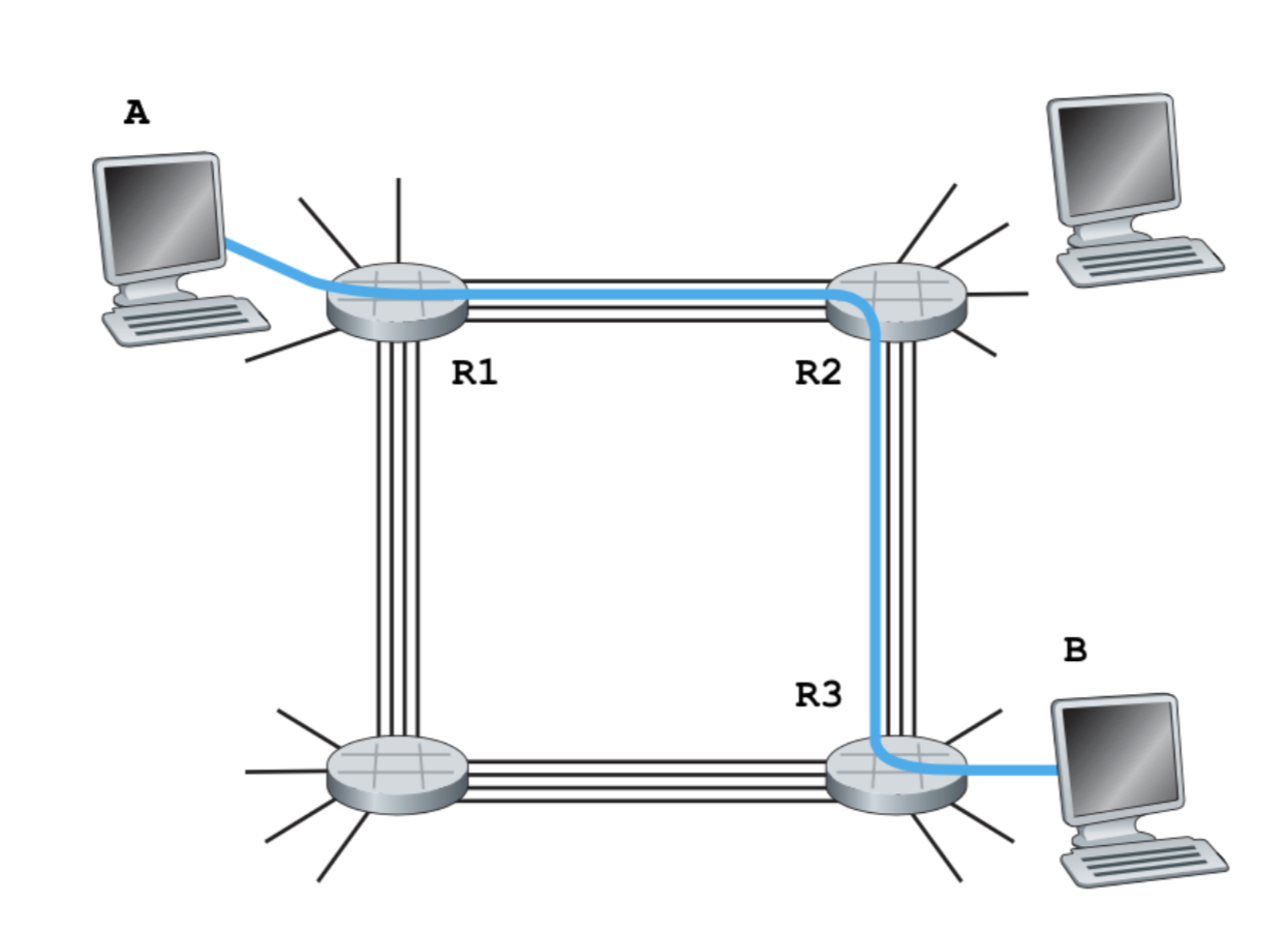
In the figure above, there are three resources (routers / switches) that’s required for host A and B to communicate. For as long as A and B are communicating, the three resources: R1, R2, and R3 are reserved for them.
An example of a circuit-switched network is the traditional analog telephone network, and the GSM (Global system for mobile communication, a.k.a 2G):
- You need to establish connection at first
- And then you have constant bandwidth
Much of the communication infrastructure has moved towards packet-switched technologies, but circuit switching remains relevant in specific contexts: emergency services or secure government communications, rural or remote areas telephony, industrial and legacy systems.
The advantage of circuit switching is that we have a guaranteed stable connection for that reserved slot / bandwidth.
The drawback of circuit switching is that user \(i\) cannot utilize the resources that user \(j\) has in the other time slot or frequency band. It is possible for a user to underutilize its resources, not to mention that it is expensive.
Multiplexing the Circuit
If there’s other hosts that would like to communicate using these resources R1, R2, and R3, host A and B must somehow share this resource, albeit being reserved. We can do this using either of the two methods:
- Frequency division multiplexing (FDM): each circuit continuously gets a fraction of the bandwidth (e.g: 4KHz as shown), or
- Time division multiplexing (TDM): each circuit gets all of the link bandwidth periodically during brief intervals of time slots.
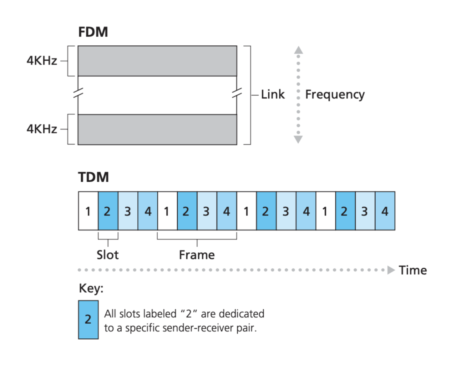
Example Calculation
Suppose Host A needs to send 128 MB (Mega Bytes) to Host B through a circuit switched network using TDM: 24 slots per second, with bit rate1 of 48Mbps (Mega bits), and 800 ms is required to establish an end-to-end connection. How many seconds are required in total to transfer all the data?
Answer: TDM
Per second, the amount of data that can be sent out from Host A to Host B is: \(\frac{1}{24} \times 48 = 2\)Mbps.
Therefore, we need \(128\times8/2 = 512\) seconds to transfer all the data. Given that we need 800ms of connection establishment time, the total transfer time becomes \(512 + 0.8 = 512.8\) seconds.
Now, suppose using circuit switched network using FDM instead: given 24 frequency bands in total, with bit rate of 48Mbps and 800ms to establish an end-to-end connection, let’s compute the seconds required in total to transfer all the data.
Answer: FDM
The speed of transfer per band is computed from dividing the original bandwidth with the number of bands available, hence we have \(48/24 = 2\)Mbps per band.
Therefore, we also need \(128\times8/2 + 0.8= 512.8\) seconds to transfer all the data, same as TDM.
This examples show you that neither method is faster than the other given similar specifications.
More Example Application
Traditional Telephony can utilize both Frequency Division Multiplexing (FDM) and Time Division Multiplexing (TDM), depending on the specific technology and infrastructure in use.
Radio and television broadcasting utilises FDM, in which multiple radio signals at different frequencies pass through the air at the same time. Another example is cable television, in which many television channels are carried simultaneously on a single cable.
The RIFF (Resource Interchange File Format) audio standard utilises TDM, where it interleaves left and right stereo signals on a per-sample basis. The Microsoft implementation is mostly known through container formats like AVI, ANI and WAV, which use RIFF as their basis.
Packet Switching
Packet Switching
Packet switching is a method of data transmission where messages are broken into smaller packets, sent independently over a network, and reassembled at the destination.
It is an alternative way to share resources between end hosts (apart from circuit switching). Remember that the internet is a shared resource. It does not belong to just 1 or 2 end hosts.
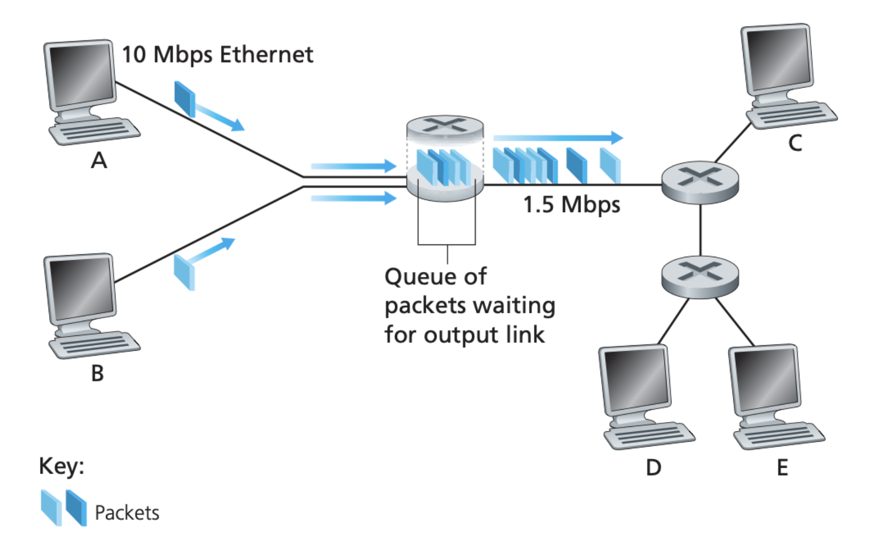
As you can see in the figure above, unlike circuit switching, packet switching resources are shared among many end users. Packets occupy network resources on demand. This is better for bursty data.
Modern internet we know today fundamentally relies on packet switching to efficiently manage data transfer across its vast network of computers and other devices.
Example Calculation
To understand how packet switching works, let’s use the original scenario where Host A needs to send 128MB to Host B using packet switching. However, the required resources are shared among 5 users.
We are given the prior knowledge that users will use 10MBps if they are active, and that they are only active 20% of the time. How long will it take for Host A to send all the data to Host B?
We cannot compute the answer right away. We need to first compute the probability of \(N\) users being active at the same time using binomial distribution:
- P(1 user is active): \(\binom{5}{1}\times(0.2)^1\times(0.8)^4\)
- P(less than 3 users are active): \(\binom{5}{0}\times(0.2)^0\times(0.8)^5 +\) \(\binom{5}{1}\times(0.2)^1\times(0.8)^4 +\) \(\binom{5}{2}\times(0.2)^2\times(0.8)^3\)
- P(exactly \(N\) out of \(M\) users are active): \(\binom{M}{N}\times(0.2)^N\times(0.8)^{M-N}\)
- P(less than \(N\) out of \(M\) users are active): \(\sum_{i=0}^{N-1} \binom{M}{i} \times(P_{active})^i\times(1-P_{active})^{M-i}\)
From this, we know that the time taken to transfer 128MB between host A and host B varies, depending on how many users are currently active.
It is non-trivial to compute it. The field that deals with this is called statistical multiplexing, a phenomenon whereby sources with statistically varying rates are mixed or input into a common server or buffer.
Comparing Circuit Switching with Packet Switching
Packet switching is better for bursty data whereas circuit switching is better for continuous streams of data. The pros and cons for each method depends on your internet usage pattern.
Packet switched networks are cheaper than circuit switched networks, as cost is shared among many users for packet switched networks. However, in a packet switched network, you only have a fluctuating effective network speed, since the resources along the network path are not reserved and it depends on how many users are currently active.
Web Browsing Traffic Pattern
The data traffic pattern when surfing the web is bursty:
- Load page once, read and scroll
- Load another link, read and scroll, repeat
The data traffic pattern when you are playing an online game, making conference calls, or downloading contents of the web leans towards continuous stream of data. A circuit switched network is therefore more ideal for this, however, since this requires “reservation” of resources along the network path and it is much more expensive.
Network Layering
Network Layering
Network layering is a design principle in computer networking where each layer of a network architecture performs specific functions and only interacts with the layers directly above and below it.
We need it to manage complex interactions between numerous network components.
It is apparent that the Internet is an extremely complicated system (hundreds of billions of devices involved). We have seen that there are many pieces/modules that forms the Internet: numerous applications and protocols, various types of end systems, packet switches, and various types of link-level media/materials.
Modules?
When discussing the “modules” in the Internet, it could refer to various hardware and software components that are necessary for the Internet to function.
These include:
- Routers and switches, which direct data traffic.
- Servers, which store and deliver content such as websites.
- Transmission media, such as cables and wireless signals that carry the data.
- Protocols, such as TCP/IP, which define the rules for transmitting data.
In programming, we try to tackle complicated systems all the time by making our code more modular. However, modularity is not the answer to organise the internet architecture because:
- Modules can interact with every other modules, that means we need to consider \(N^2\) possible interactions between N modules.
- Due to point (1), you may result in emergent behaviour:
- Erroneous behaviours that aren’t observed in the modules individually, but arise when you let one module interact with another (you suffer from this a lot from 50.002 1D project).
- Example: priority inversion caused by priority scheduling + locking mechanism (recall the OS topics). This caused something important (of a higher priority) to inadvertently become the lowest priority due to some misguided usage of locking mechanism. Head to class activity to find out more.
Due to the vast size of components making up the internet (or network of internets), breaking them into modules is simply not enough. Plus, we cannot possibly think of all possible emergent behavior that may arise from making these modules interact.
The solution is to allow layering:
- Layering reduces interactions between sub-components
- Each layer relies on the services of the layer directly below it
- With \(N\) layers, there’s only \(N-1\) interactions that we need to consider
A real life example will be the airline layering of airline functionality:
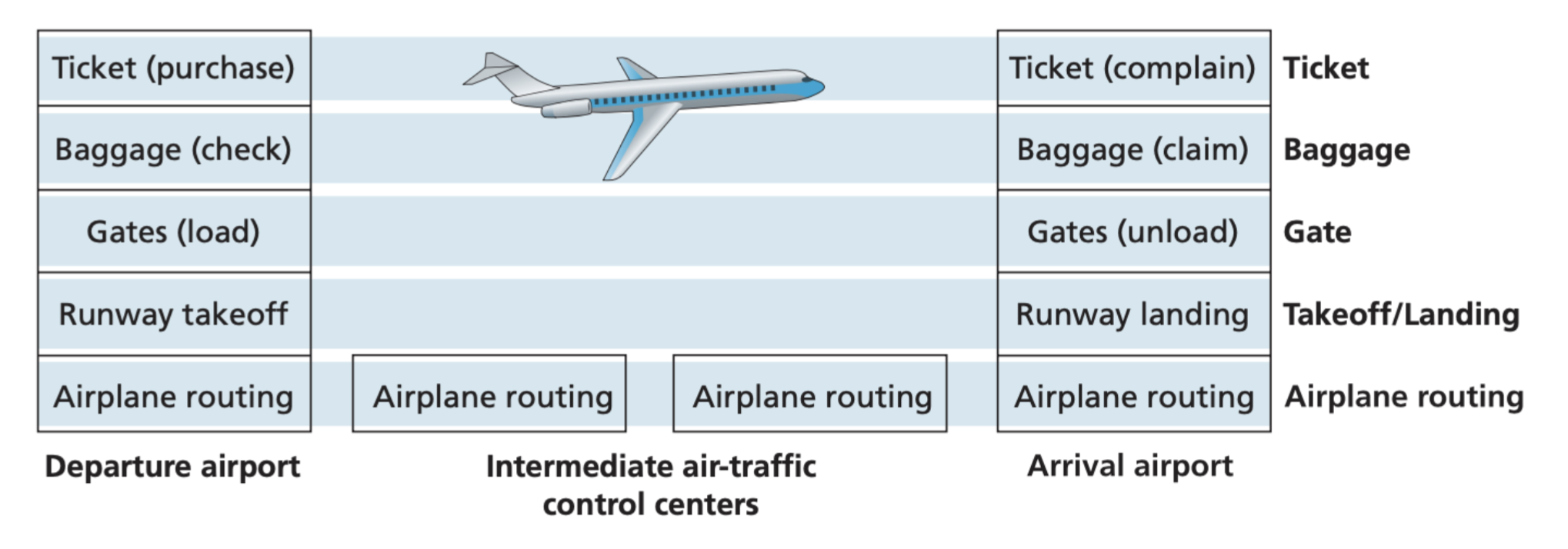
The 5 Layer OSI Model
In this course, we learn the 5-layer internet protocol stack comprised on application layer, transport layer, network layer, link layer, and physical layer. They’re usually known as the OSI (Open Systems Interconnection) model (5-layer version).
Application Layer
This is implemented as software, typically the user application(s) needing to communicate via the internet itself. This layer is where network applications and their application-layer protocols reside: the layer that provides APIs for web-applications to rely on.
Examples of protocols in the Application Layer and their associated libraries/frameworks:
- HTTP (Hypertext Transfer Protocol): used for transmitting hypertext documents on the World Wide Web.
- Libraries/Frameworks: Express.js (Node.js), Flask (Python), Spring Boot (Java), Django (Python), Ruby on Rails (Ruby), ASP.NET (C#), etc.
- SMTP (Simple Mail Transfer Protocol): used for sending email messages between servers.
- Libraries/Frameworks: JavaMail (Java), Flask-Mail (Python), Nodemailer (Node.js), Spring Mail (Java), etc.
- FTP (File Transfer Protocol): used for transferring files between a client and a server on a computer network.
- Libraries/Frameworks: Apache Commons Net (Java), ftplib (Python), Net::FTP (Perl), libcurl (C/C++), etc.
- DNS (Domain Name System): used for translating domain names into IP addresses and vice versa.
- Libraries/Frameworks: dnsjava (Java), dnspython (Python), Net::DNS (Perl), etc.
- SSH (Secure Shell): used for secure remote access and secure file transfer over an insecure network.
- Libraries/Frameworks: JSch (Java), Paramiko (Python), Net::SSH (Perl), etc.
- WebSocket: provides full-duplex communication channels over a single TCP connection.
- Libraries/Frameworks: ws (Node.js), websocket-client (Python), WebSocket API (JavaScript), etc.
An application layer packet of information is called a message.
Transport Layer
This is also implemented as software. This layer must reliably assist to transport application-layer messages between application endpoints.
Transport layer protocols are typically implemented as part of the operating system’s networking stack.
Two of the most common transport layer protocols are:
- Transmission Control Protocol (TCP): TCP is a connection-oriented protocol that ensures reliable and ordered delivery of data packets between devices. It manages data transmission, flow control, congestion control, and error detection through mechanisms such as acknowledgments, retransmissions, and sequencing.
- User Datagram Protocol (UDP): UDP is a connectionless protocol that provides a simple and lightweight method for transmitting data packets between devices. Unlike TCP, UDP does not guarantee delivery or order of packets, making it faster but less reliable. It is commonly used for real-time applications like video streaming and online gaming.
Application layer protocols rely on transport layer protocols. For instance, HTTP relies heavily on TCP for reliable and ordered delivery of web page data. On the other hand, DNS primarily uses UDP because DNS queries are typically short and require quick responses. You will learn more about these protocols specifically in the later weeks.
A transport layer packet of information is called a segment
Network Layer
The network layer can consist of both software and hardware components. Devices or softwares in this layer is responsible for routing datagrams through a series of routers between the source and destination (i.e: it does path planning).
Below are some examples:
- Network Layer Protocols: Primarily implemented in software
- IP: Routes and addresses packets across networks in the Internet Protocol Suite.
- ICMP: Provides diagnostics and error reporting within IP networks.
- OSPF: Determines optimal routing paths within autonomous systems.
- BGP: Facilitates routing between autonomous systems on the Internet.
- Network Layer Devices (e.g: these are devices made solely to support up to network layer):
- Router: Forwards data packets between computer networks based on IP addresses.
- Layer 3 Switch: Combines switching and routing functions at wire speed.
- Network Firewall: Filters and controls network traffic based on predefined security rules.
- Gateway: Acts as an entry or exit point between different networks, translating protocols or addressing schemes.
- Software (implementation):
- Routing Protocol Software such as Quagga, an open-source routing software suite that supports various routing protocols and is commonly used on Linux-based routers.
Difference with transport layer protocols: the Internet transport-layer protocols (TCP or UDP) in a source host passes a transport-layer segment and a destination address to the network layer, just as you would give the postal service a letter with a destination address. The network layer then provides the service of actually delivering the segment (now called datagram) to the transport layer in the destination host.
A network layer packet of information is called a datagram.
Link Layer
Most Link Layer utilities are implemented in hardware, such as bit error detection, with its software part implements the higher level functionality and activates the controlling hardware.
Its job is to provide reliable delivery service of packets from one node to another in the (already known) route. Link layer devices or software does not route, it simply delivers the packets of information to the next node which is already determined by the network-layer.
Below are some examples:
- Protocols:: Primarily implemented as combination of both hardware and software
- Ethernet: Manages communication over local area networks (LANs) using MAC addresses.
- ARP (Address Resolution Protocol): Maps IP addresses to MAC addresses for data transmission within a network.
- PPP (Point-to-Point Protocol): Establishes direct connections between two nodes over a serial link.
- Devices:
- Ethernet Switch: Forwards data frames between devices within a LAN based on MAC addresses.
- NIC (Network Interface Card): Connects a computer or device to a network, handling data transmission at the link layer.
- Wireless Access Point (WAP): Connects wireless devices to a wired network, managing wireless communication at the link layer.
- Ethernet Hub (deprecated): Shares network bandwidth among connected devices by broadcasting data frames to all ports.
- Software:
- NIC Driver: Implement link layer protocols such as Ethernet and provide an interface for the operating system to send and receive data frames over the network.
To move a packet from one node (host or router) to the next node in the route, the network layer relies on the services of the link layer. In particular, at each node, the network layer passes the datagram down to the link layer, which delivers the datagram (now called frame) to the next node along the route.
A link layer packet of information is called a frame.
Physical Layer
This is implemented purely as hardware.
The job of the link layer is to move entire frames from one network element to an adjacent network element, while the job of the physical layer is to move the individual bits within the frame from one node to the next.
Protocols on this layer depend on the medium of transmission: twisted pair copper wire, optical fibre, etc.
Below are some examples:
- Protocols:
- Ethernet Physical Layer: Defines the physical characteristics and transmission medium for Ethernet networks, including cable types and signaling methods.
- IEEE 802.11 (Wi-Fi): Specifies the physical layer for wireless local area networks (WLANs), including modulation techniques and frequency bands.
- Devices:
- Ethernet Cable: Transmits electrical signals between devices in an Ethernet network, such as twisted pair cables (e.g., Cat5e, Cat6).
- Wireless Antenna: Sends and receives radio signals to communicate with wireless devices in Wi-Fi networks.
- Ethernet Transceiver: Converts digital data into signals suitable for transmission over Ethernet cables, and vice versa.
- Fiber Optic Cable: Transmits data using light signals through glass or plastic fibers, providing high-speed, long-distance communication in fiber optic networks.
A physical layer unit of information is called bits.
Important Note
Note that these layers are only design principles, serving as conceptual framework for understanding the functions and responsibilities of different network protocols.
Each layer of the OSI Five-Layer Model has its own set of protocols, devices, and software that collectively implement the functionalities defined by that layer. These implementations are commonly referred to as “layer implementations” or “protocol stack implementations.”
Protocols that belong to each layer are designed to be modular, meaning they can be developed, maintained, and upgraded independently. They are also designed to scale to accommodate the growth of the internet and support a diverse range of applications and devices.
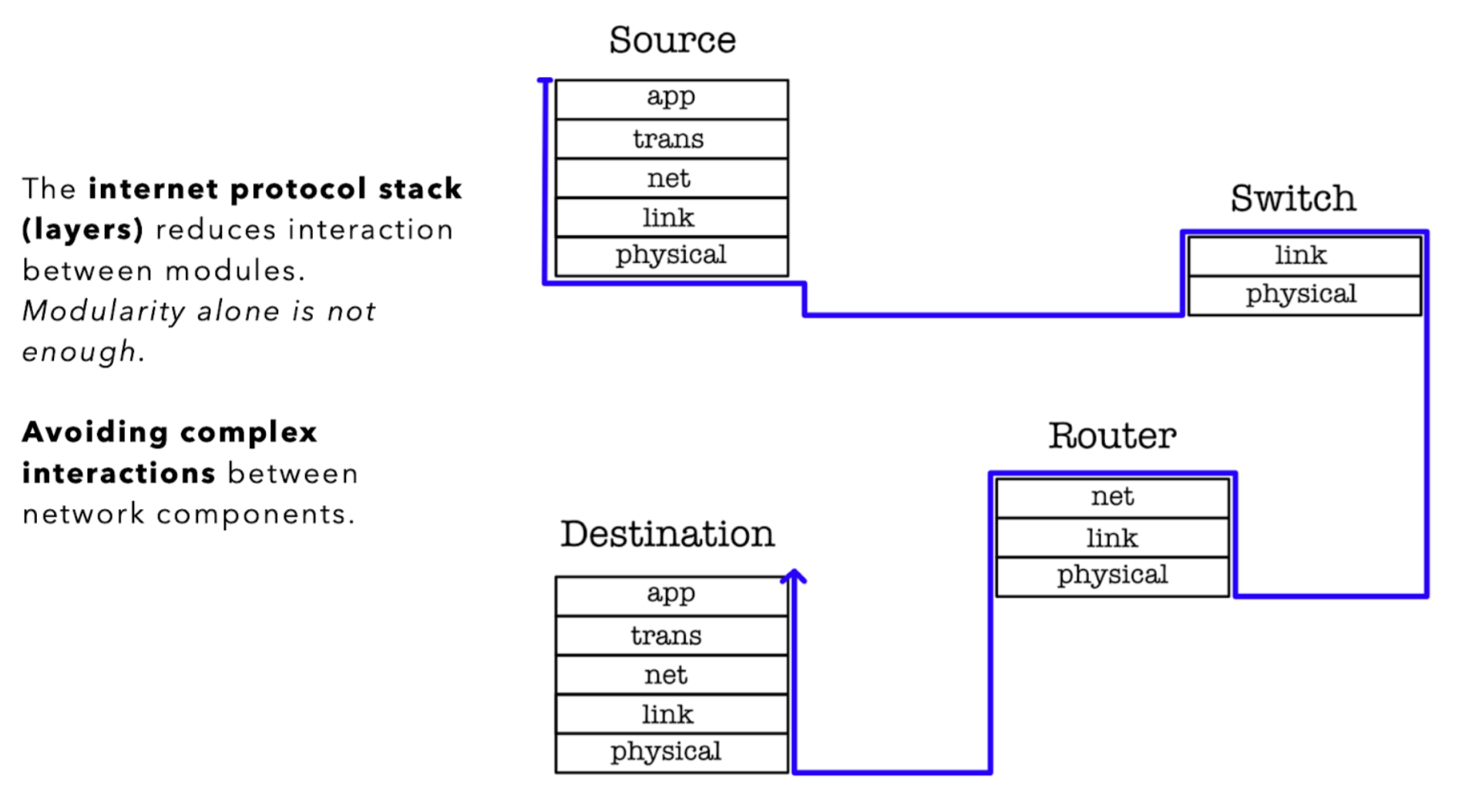
Each internet device is able to provide service up to some highest layer, for example, our computers (end hosts) implement all five layers while the router implements up to the network layer, since it obviously does not need to run any network applications (i.e: web browser) on it. The illustration below shows the highest layer implemented in each common device:
Data Encapsulation
The layers of protocols we saw above forms a protocol stack. Here’s a quick illustration to get started:
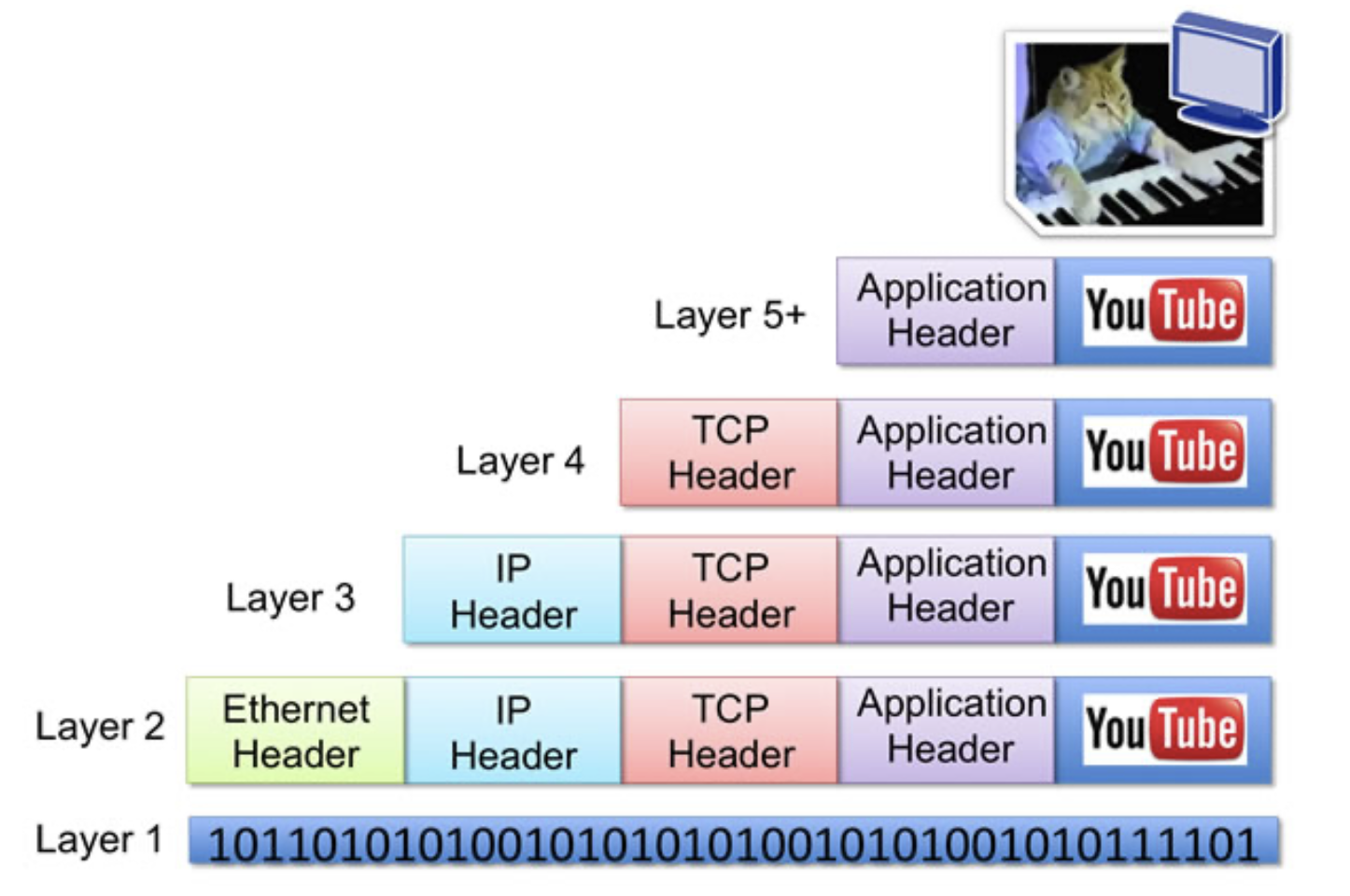
Suppose you’re watching a video on YouTube, on a system that’s connected to the internet via ethernet connection.
- Incoming data enters Layer 1 (Physical Layer) of your system (bits of data).
- Layer 2 (Link Layer) of your computer decode and strips the Ethernet header.
- Layer 3 (Network Layer) decode and strips the IP header, ensuring that your host is the intended recipient.
- Similarly for Layer 4 (your OS) to determine which TCP socket this data should be sent to.
- Layer 5 (web application like Chrome) figured out that this incoming data is meant for YouTube that’s opened in one of your 10000 opened tabs.
In a general-purpose computer, the implementation of the OSI model’s first three layers (Physical, Data Link, and Network) is typically distributed between the network interface card (NIC) and the computer’s operating system (OS).
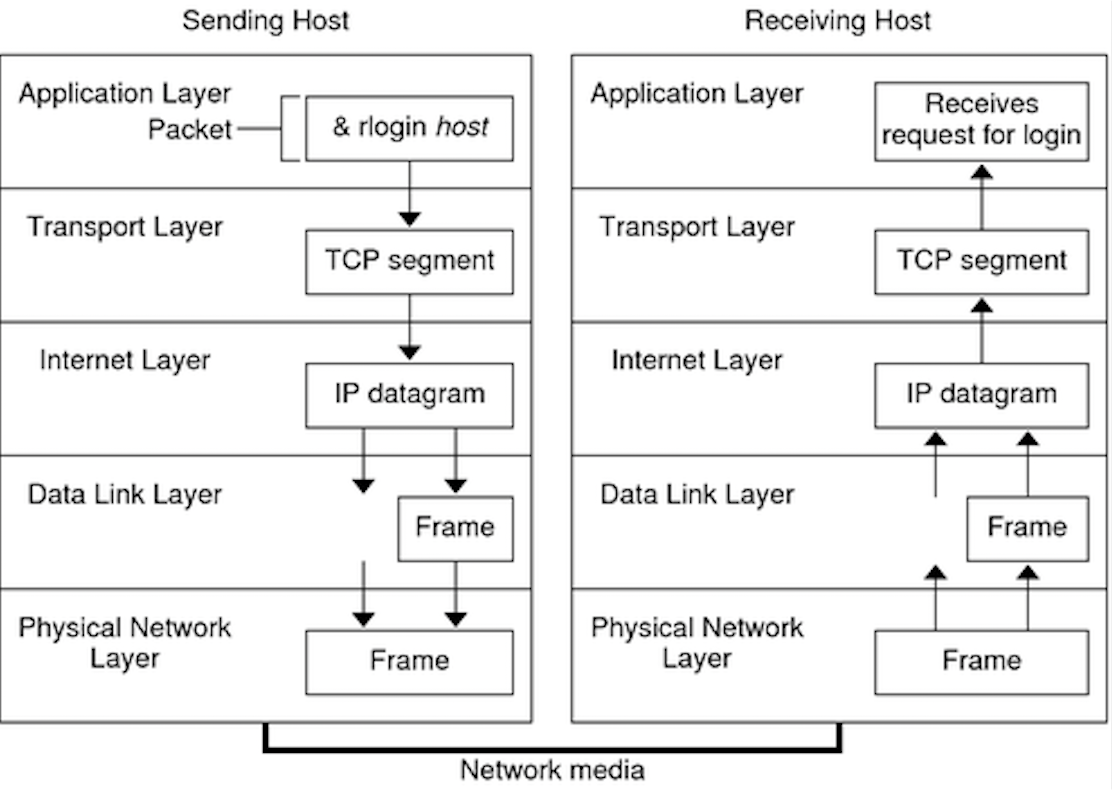
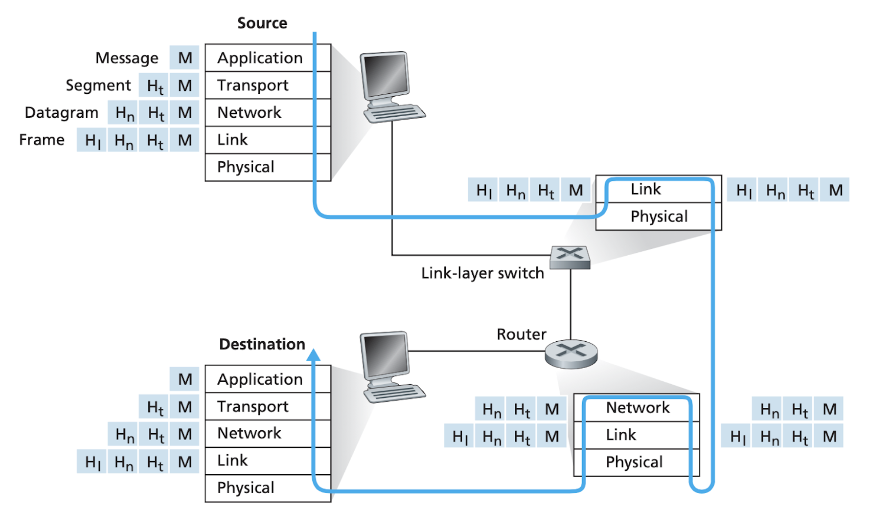
The figure below shows the physical path that data takes down a sending end system’s protocol stack, up and down the protocol stack of an intervening link-layer switch and router, and then up the protocol stack at the receiving end system.
Data encapsulation
As the packet goes down the protocol stack, a header is added by each layer (protocol). As it goes up the protocol stack, each layer strips off its header.
This is called data encapsulation.
We see that at each layer, a packet has two types of fields:
- Header field: header meant for this layer to process
- Payload field: a packet from the layer above.
With layering, header vs. payload size is now relative to the layer; e.g., the transport layer’s data (header + payload) becomes the network layer’s payload.
Software-Defined Networking (SDN)
Modern internet still follows layering roughly, but there can be significant departure as well like SDN.
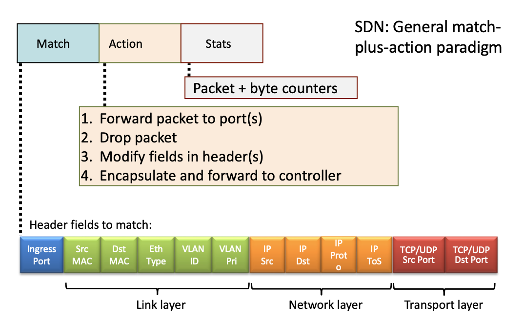
Software-Defined Networking (SDN) is a modern networking architecture that separates the control plane from the data plane in network devices.
This separation allows for more flexible and efficient network management.
- In SDN, a centralized controller dynamically manages network behavior through software applications, providing a global view and centralized control over the network.
- This approach enhances scalability, simplifies network management, improves resource utilization, and enables rapid innovation by allowing network administrators to programmatically configure and manage network services.
- SDN is widely used in data centers, cloud environments, and enterprise networks to support dynamic, scalable, and automated network operations.
Summary
We have learned about network basics in this chapter, both from its nuts and bolt view and service view.
There are many challenges in maintaining a huge network of devices, they include: operability, sharing, complex interacting component, and scalability. We carefully study each challenge and present you with various practical ways to approach the challenge: via protocols, TDM, FDM, packet switching, and network layering among many others. It is important to appreciate the scale of these challenges and the pros and cons of each proposed solution.
Key learning points from the “Network Basics” note include:
- Components of Networks: Introduction to the core elements of networks such as hosts, routers, and packet switches.
- Network Layering: Explanation of the layered architecture, which organizes communication systems into hierarchical layers, each with specific functions.
- Data Transmission Methods: Detailed look at packet switching and circuit switching, highlighting the differences and applications of each method in data communication.
Appendix
Connecting Modem, Router, Switches, and End Hosts
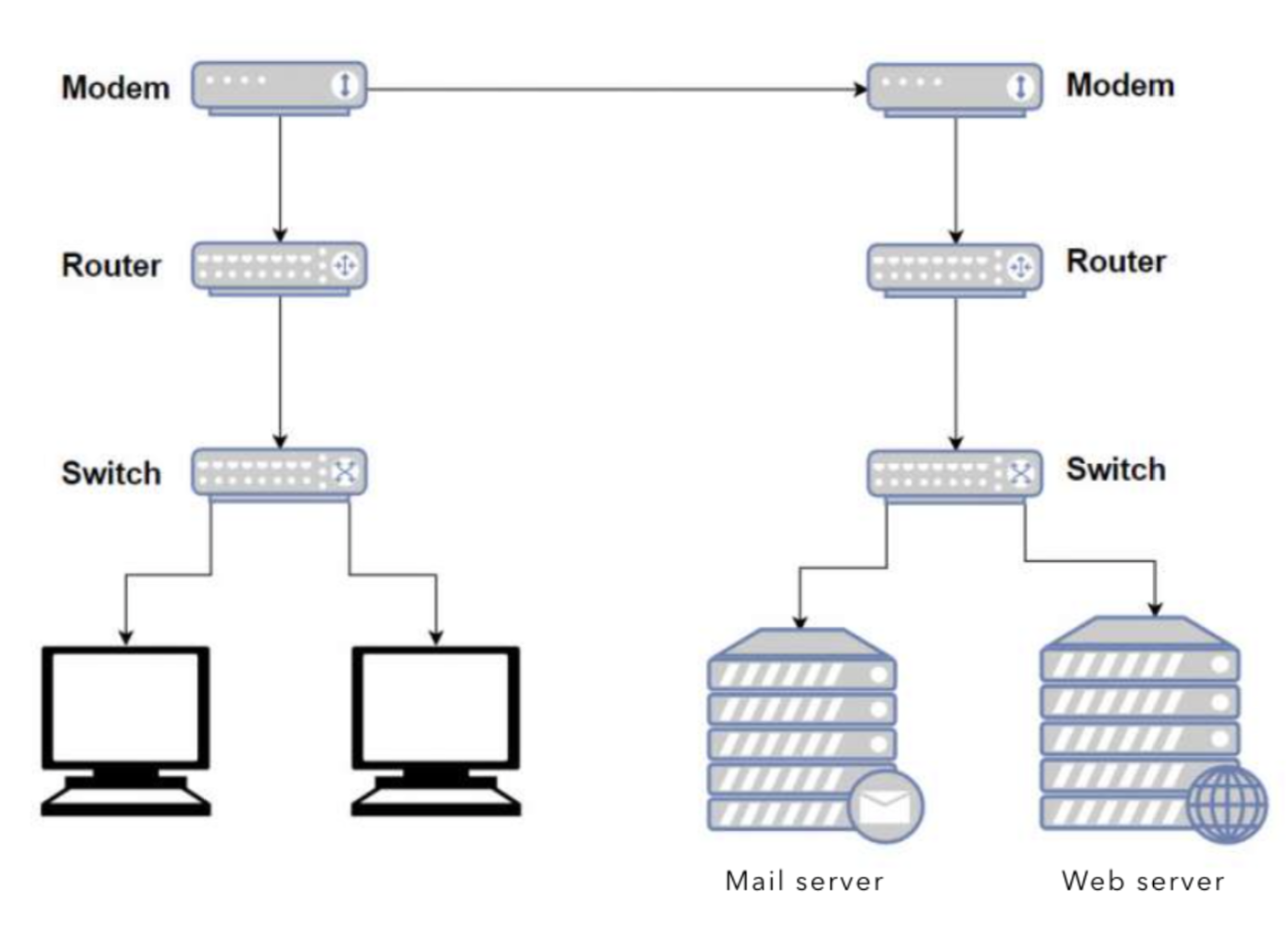
Modem (modulator demodulator) is the device that’s connected to the ISP (not drawn above), and it is used to connect your ISP using a phone line (for DSL), cable connection or fiber (ONT). Its job is mainly to convert analog to digital signals . A modem has a single coaxial port for the cable connection from your ISP and a single ethernet port to link the Internet port on your router. Recall when you subscribe to an ISP, e.g: Starhub, Singtel, etc you will be given these modems that are supported by the ISP.
Router is what you can use to route packages towards devices within your network system. It resolves IP addresses and route packages accordingly to end hosts within your network while modem does not. If your network system consists of more than one devices, your router will give each device a different internal IP addresses, for example, by connecting to SUTD_Wifi, an end host is given the internal IP: 10.19.24.59

Other hosts connected to this router will have a similar IP address, e.g: 10.19.24.63. All devices connected to the same modem have the same public IP to the outside world.
Finally, switches are used when you want to connect multiple devices to a router. Modern routers also include switches, e.g: wireless routers allow multiple devices to connect to it.
Unlike routers, a switch doesn’t solve IP and try to find a route. The switch simply maps multiple MAC addresses to a port. It has some sort of dynamic look-up table and it just forwards packets where it is asked to forward to, based on MAC address.
We do not dive too deep into details on how routers and switches work in this course. You can learn more about how switches and routers work in specialised Computer Network courses.
-
Defined as the number of bits that a link can support per second. ↩
 50.005 CSE